Avtech pulse generators with the "-B" suffix (i.e., with IEEE-488.2 GPIB control) with firmware revision 1.88 or higher have user-adjustable timing calibration. (Use the "*idn?" command to determine your firmware revision number.)
Locating the Calibration Signal Point
The calibration is adjusted by observing the TTL-level (0 and +3V levels, nominally) trigger signal inside the instrument on an oscilloscope. To access the appropriate testpoint, remove the top cover of the instrument. Locate the 4" by 10" control board on the right side of the instrument, and examine the front end of the board. Older instruments will have a board that looks like the one in Figure 1 - the testpoint that must be monitored is highlighted with an arrow. On this older board, the testpoint is a 0.1" by 0.1" solder pad. The user may need to solder a short piece of hookup wire to the pad to facilitate probing. Newer instruments have a more convenient test-loop, to which a probe may be attached directly, as shown in Figures 2A, 2B, and onwards (which show different generations of the same basic circuit board):
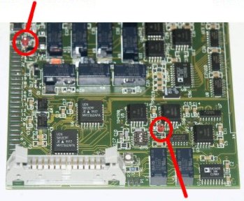
| Figure 1 - PCB #86 | 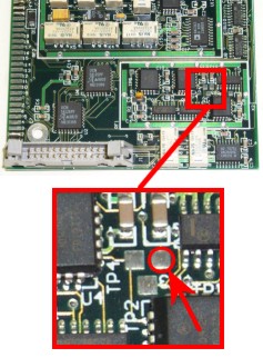 Main test loop (for single-channel units and CH1 of dual-channel units) |
| Figure 2A - PCB #108 | 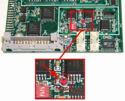 Main test loop (for single-channel units and CH1 of dual-channel units) |
|
Figure 2B - PCB #108B |
SYNC test loop |
|
Figure 2C - PCB #108E |
SYNC test loop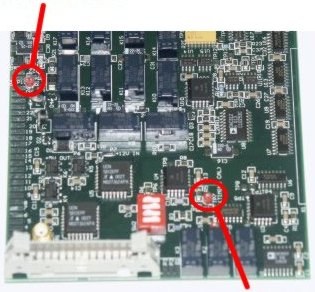 Main test loop (for single-channel units and CH1 of dual-channel units) |
|
Figure 2D - PCB #108G |
SYNC test loop Main test loop (for single-channel units and CH1 of dual-channel units) |
|
Figure 2E - PCB #108M4 |
SYNC test loop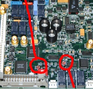 Main test loop (for single-channel units and CH1 of dual-channel units) |
|
Figure 2F - PCB #108N |
SYNC test loop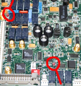 Main test loop (for single-channel units and CH1 of dual-channel units) |
|
Figure 2G - PCB #108Q |
SYNC test loop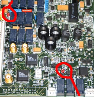 Main test loop (for single-channel units and CH1 of dual-channel units) |
When accessing the internal testpoint, be careful not to touch any other wiring. Connect the oscilloscope probe while the instrument is turned off. Connect the ground clip of the probe to the instrument chassis. (The flanges which mate to the cover screws are convenient grounding points.) Then turn the instrument on and perform your measurements safely away from the instrument.
Adjusting the Pulse Period / Frequency Calibration
To adjust the pulse period calibration, send the query:
diag:pulse:period:cal:point? max
and note the returned number, N (typically 16, 24 or 32). This is the number of calibration points that must be checked.
For the first calibration point, send the command:
diag:pulse:period:cal:point 1 go
The instrument will set the frequency to the first calibration point. The duty cycle of the signal with be approximately 40%, to allow easy viewing on an oscilloscope. The nominal frequency may be determined by sending the query:
pulse:period?
This information can be used to set your oscilloscope to the appropriate time scale.
Using your oscilloscope, determine the actual period observed at the calibration testpoint. Compare the measured value to the nominal value, and make sure that the difference between the two is less than either 30 ns or 20%.
For example, assume that you measured a period of 88.3 ns. Update the calibration by sending the command:
diag:pulse:period:cal:point 1 88.3e-9
Do not use any units. This will update the calibration for point 1 (of N, typically 16, 24 or 32).
Repeat these commands for points 2 to N, replacing the "1" in each of the commands above with the appropriate number.
Note: Avtech function generators (i.e, the AV-151 and AV-153 series) do not use points 1 and 2. Skip them, and calibrate 3 to N instead.
Adjusting the Pulse Width Calibration
The procedure for adjusting pulse width is similar, except that the word "period" in each command is replaced with "width". That is,
diag:pulse:width:cal:point? max
diag:pulse:width:cal:point 1 go
pulse:width?
diag:pulse:width:cal:point 1 8.7e-9
If your instrument is a dual-channel model, the pulse width of the second channel may be adjusted by appending the channel modifier "2" to the commands, like so:
diag:pulse:width:cal:point2? max
diag:pulse:width:cal:point2 1 go
pulse:width2?
diag:pulse:width:cal:point2 1 8.7e-9When calibrating channel 2, the oscilloscope probe must be connected to the CH2 test point. This is located in different locations, depending on the instrument. Contact Avtech with your instrument's model number and serial number for details.
Adjusting the Pulse Delay Calibration
The procedure for adjusting pulse width is similar, except that the word "width" in each command is replaced with "delay". Measure the observed pulse width on the oscilloscope, and update the delay calibration with the observed width.
diag:pulse:delay:cal:point? max
diag:pulse:delay:cal:point 1 go
pulse:delay?
diag:pulse:delay:cal:point 1 16.5e-9
Calibration Safeguards
During calibration, the output is automatically switched off. Calibration adjustments greater than 20% may be rejected by the instrument. Calibration adjustments which would prevent operation at the minimum and maximum limits of the parameter will also be rejected.
Automating the Calibration Process
The calibration process lends itself naturally to automation with LabView, or other similar packages. A sample LabView 5.1 calibration routine is available. To use it, connect the Avtech instrument and a Tektronix TDS3X0 oscilloscope (such as the TDS350 or TDS360) via the GPIB bus, connect the CH1 oscilloscope probe to the calibration testpoint, and run the top-level VI. It will automatically calibrate the period, width, and delay settings. The routine can be set to calibrate dual channel instruments.
The routine can be modified by the user to accommodate other oscilloscopes.
Please report any bugs in the sample code to mjc@avtechpulse.com.
Other Calibration Commands
The process described above calibrates the internal TTL-level trigger signal. Some pulse width compression may occur in the output stage circuitry of the instrument. For instance, if you have performed the above process, and you find that all output pulse widths are too narrow by 3.6 ns, send this command to correct it:
diag:pulse:width:cal:shift -3.6e-9
If the output is too wide, send:
diag:pulse:width:cal:shift +3.6e-9
Dual-polarity instruments with firmware version 4.08 and later have separate pulse-width shift settings for the positive and negative modes. Prior versions have a single setting. For these newer dual-polarity instruments, the pulse width shift command should be sent once while the amplitude is positive, and once while the amplitude is negative.
Certain instruments have a large shift. The AVL series in particular may require shifts of -50 to -70 ns.
This command is not included in the LabView routine mentioned above.
Calibration Intervals
If you are required to calibrate your instruments on a regular schedule, Avtech suggests 1 year as an appropriate time between calibration checks. The instrument should first be checked to see if the calibration has slipped beyond an acceptable range. If it is within an acceptable range, do not perform the above procedure.
The above process should only be performed when required, since it requires internal access to the instrument, and since it is possible for an end-user to defeat the numerous built-in safeguards and de-calibrate the instrument to a point where it requires adjustment at the factory.

