This section provides general guidance in connecting a variety of loads to the outputs of ultra-fast rise time AVTECH pulse generators (100 ps to 1 ns). Fifty Ohm loads, low impedance loads such as laser diodes, and high impedance loads such as CRT and photomultiplier grids are considered in particular. The use of Avtech bias insertion units, matching transformers, inverting transformers, low-impedance AV-LZ lines and power splitters is also discussed. The application of AVTECH pulse generators to pulsed laser diode driving and to switching time testing of semiconductor diodes and transistors is included as well. But to begin with, we first define the pulse parameters rise time and pulse width and we then consider the topics of oscilloscope bandwidth and the probing of ultra high speed voltage and current waveforms.
A) RISE TIME, FALL TIME AND PULSE WIDTH DEFINED
Rise and fall time are the interval between the 20% and 80% amplitude points on the leading and trailing edges of a pulse. This interval (rather than 10% to 90%) is employed so as to avoid the preshoot perturbation which precedes the rising (or falling) transition of many ultra fast waveforms. Unless otherwise specified, the pulse width is defined as the interval between the 20% amplitude points on the leading and trailing edges.
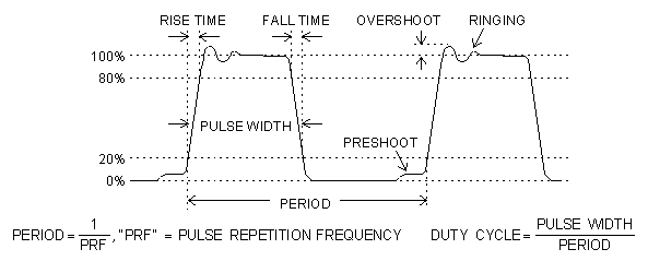
Fig. 1 Pulse Parameter Definitions
B) OSCILLOSCOPES AND PROBES
In order to display a fast rise time waveform (without significant degradation) the bandwidth of the oscilloscope probe, cable and attenuator must exceed the following:
BW ≥ 1 / tR
where tR is the rise time of the input waveform. For example, for a 100 ps rise time waveform the bandwidth of the display system should exceed 10 GHz. For factory testing purposes on 100 ps rise time generators, Avtech normally employs sampling oscilloscopes with bandwidth in excess of 12 GHz or 18 GHz. The following sampling oscilloscope systems satisfy the above requirements:
-
Tektronix S4, 7S11, 7T11 (with a 7000 series mainframe)
-
Tektronix 11801B with SD22 (or equivalent)
-
Hewlett Packard 54120 series.
Of course, the bandwidth of the cables, probes and attenuators (if any) must be considered as well since the overall display system rise time is given by the root of the sum of the squares as follows:

which should be less than one-third of the waveform rise time TRW. For factory testing of 100 ps rise time units Avtech normally employs attenuators with 18 GHz bandwidth and SMA connectors (from suppliers such as Midwest Microwave and Hewlett Packard).
For all oscilloscope systems, the displayed waveforms will be degraded by jitter unless exceptional care is taken to properly set the triggering controls on the oscilloscope and the pulse generators (as per the respective instruction manuals). Fast rise times -C units contain a low jitter clock to help in this regard. AVTECH pulse generators without internal clocks (-PS units and modules) should be triggered by low-jitter sources such as the AVTECH AV-1000-C which includes the necessary delay and sync controls.
For lower-speed applications (e.g. rise time of several nanoseconds) digital scopes have largely replaced analog scopes. Care should be taken with digital scopes when studying high amplitude waveforms (e.g. 10 and 100 Volts) not to exceed the rated input amplitude as this may result in a "scrambled" output.
The problem of displaying a fast rise time current waveform is even more difficult than displaying a voltage waveform. The TEKTRONIX CT-1 current probe is recommended for waveforms as fast as about 500 ps. For faster waveforms, it is recommended that the voltage across a current sensing resistor be displayed. This resistor should be as large as possible (e.g. 50 Ohms is ideal) rather than low (e.g. 1.0 Ohm) as spikes or severe overshoot may be observed on the rising and falling edges when employing a 1.0 Ohm sensing resistor in a 50 Ohm circuit.
C) LOAD IMPEDANCE
Most high-speed Avtech pulse generators (those with rise times of less than 10 ns) are designed for operation into 50 Ohm load impedance. To avoid pulse degradation and possible damage to the pulse generator or load, care should be taken to ensure that the load (including any attenuators, cables and connectors) exhibits adequate average AND peak power ratings, as well as sufficient bandwidth rating (e.g. in excess of 10 GHz for 100 ps rise time units).
It is often desirable to use Avtech 50 Ohm pulse generators to pulse very high impedance loads (e.g. photomultiplier tubes or CRT loads) or very low impedance loads such as laser diodes. This may often be accomplished by means of either a shunt 50 Ohm resistor, a series 50 Ohm resistor, an Avtech pulse transformer or combinations of resistors and transformers. The use of pulse transformers is discussed in a following section while the application of shunt and series 50 Ohm resistors is illustrated in Figs. 2 and 3.
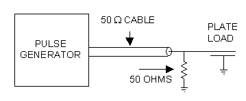
Fig. 2 Use of a 50 Ohm shunt resistor to match an Avtech pulse generator to a high impedance load.
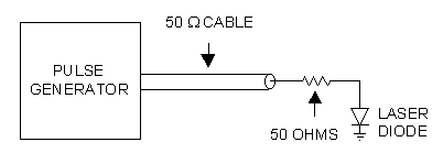
In Fig. 2 a 50 Ohm resistor with a bandwidth compatible with the pulse generator rise time is placed across a high impedance plate load to eliminate any possible reflections from the load. In Fig. 3, a 47 to 51 Ohm resistor is placed in series with a laser diode load to provide a matched load for the pulse generator. In all cases, the resistor (and diode) leads must be extremely short (less than 0.1 inches for AVL, AVR and AVI applications) and still less for AVP, AVM and similar fast rise time applications. For AVL, AVR and AVI units, a 1/4 or 1/2 Watt carbon composition resistor may suffice. For faster pulse generators (e.g. 100 ps rise time units), a thin film or thick film microwave rod resistor should be used. Suitable rod resistors are manufactured by KDI Pyrofilm Inc.
Methods for introducing a DC bias or offset to the loads shown in Figs. 2 and 3 are described in the following section. It is critically important to note that some pulse generators have an AC-coupled output stage and so when connecting a laser diode as shown in Fig. 3, it is essential that a DC path be provided for the laser diode current. This path can be provided using the AVX-T method shown in Fig. 5 or by the addition of a shunt 1 kΩ resistor to ground at the input to the 50 Ohm resistor. Without the DC path the diode rise time may be severely degraded and in fact the diode may not lase.
Note that Avtech now offers the AVX-S series bias insertion units (and the AVO-9-C pulse generator series) which provide the impedance matching and DC path considerations in addition to convenient socket mounting of the laser diode (see pages 74, 75, 64 and 65).
D) INTRODUCING DC BIAS OR OFFSETS TO LOADS CONNECTED TO AVTECH PULSE GENERATORS
It is often necessary to introduce a DC bias or offset to the types of loads shown in Figs. 2 and 3. This can often be accomplished by using an Avtech Model AVX-T bias insertion unit or by using an Avtech pulse generator equipped with the -OS option (i.e. bias insertion option). Techniques for connecting an Avtech 50 Ohm pulse generator and a bias insertion unit to high and low impedance loads are illustrated in Figs. 4 and 5.


It should be noted that instruments with the -OS option include the bias insertion function within the instrument mainframe. In the case of a high impedance load it is generally necessary to place a DC blocking capacitor in series with the 50 Ohm resistor used to shunt the load. This blocking capacitor prevents a large DC current from flowing from the bias supply through the 50 Ohm resistor and to ground. The DC bias which is applied at the DC IN terminals of the bias insertion unit appears directly across the high impedance load. In some applications, this DC bias may gate a tube off while the pulse which is introduced by the pulse generator may overcome the bias and gate the tube on for the duration of the pulse.
In the case of a low impedance load such as a laser diode, the series 50 Ohm resistor serves to define the DC bias current as well as prevent pulse reflections as described in the previous Section. To a first approximation, the diode DC current is given by:

The bias voltage is adjusted to yield the required DC diode current. The power rating of the resistor must exceed the product of VBIAS and Idc.
To a first approximation, the diode peak pulse current is given by:

It should be noted that some AVTECH pulse generators may be equipped with the output monitor option (-M) which provides a 20 dB attenuated (i.e. x 10) replica of Vpulse which may be monitored on a scope to determine the precise amplitude and pulse width while the diode load is connected. Alternatively, a Tektronix CT-1 current probe may be used. For greater convenience the AVX-S series of bias insertion units (see pages 74 and 75) should be used since these include a current monitor as a standard feature. Note that for high current applications most AVO-7, AVO-8 and AV-108 units are available with a precision current monitor option.
F) OUTPUT POLARITY INVERSION USING AVTECH INVERTING TRANSFORMERS
Many Avtech pulse generator models are now available with a dual output polarity option (i.e. positive and negative). For units not equipped with this option, the AVX-1, AVX-3 or AVX-R series inverting transformers may generally be used to invert the pulse polarity with minimal degradation.
H) LASER DIODE DRIVING
The following three basic types of Avtech pulse generators are often used for high-speed and/or
high-power pulse driving of laser diodes:
-
50 Ohm pulse generators (e.g. AV-1020-C, AVM, AVP, AVO-9 series).
-
Pulsed constant current generators (e.g. AV-155, AV-156, AV-106, AV-107 and AV-108 series).
-
Pulsed constant voltage generators (e.g. AV-1010-B, AVR, AVO-6, AVO-7 and AVO-8 units).
Each of these three applications is briefly discussed in the following paragraphs. The range of available amplitudes, pulse widths and rise times is outlined in the selection guide on page 4 of this catalog.
Fifty Ohm applications are perhaps the most common and are mainly concerned with currents of less than about one Ampere and with fast rise times (e.g. sub nanosecond). The basic, essential techniques for connecting a laser diode to a high speed 50 Ohm pulse generator are discussed in Sections C and D of this Applications Guide (see Figs. 3 and 5). Avtech offers the AVO-9-C pulse generator series (see page 64) and the AVX-S series of bias insertion units (see page 74) which include the necessary impedance matching, DC path considerations and socket mounting of the diodes. The basic functional equivalent circuits of the bias insertion units are shown in Figs. 8 and 9.
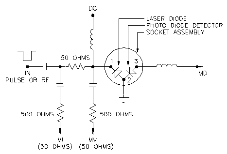
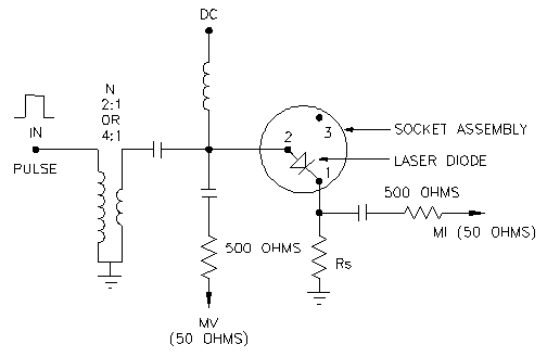
Fig. 9 AVX-S3 functional equivalent circuit. For currents to 28 Amps and nanosecond rise times.
The current monitor (MI) allows the user to monitor the diode current. The diode current is
dependent upon the diode voltage (as well as upon the driving potential and the resistive elements). For
applications where the diode current must be totally independent of the diode voltage, Avtech offers the AV-155,
AV-156, AV-106, AV-107 and AV-108 series which provide pulsed constant current pulses. These units are normally
intended for applications requiring rise times of 10 ns or higher, peak diode currents in the range of 1 to 200
Amperes and pulse widths in the range of 100 nanoseconds to one millisecond. The diode is connected directly to the
output terminals (which is normally a 1 centimeter length of low impedance microstrip protruding from the output
module). Considerable care must be taken to employ very short low inductance loads to avoid the inductive voltage
kick predicted by LENZ'S LAW ![]() for a high
rate of change of current in an inductive circuit. For application when the diode load can not be affixed directly
on the terminals of the output module, Avtech's AV-LZ1 line of ultra-low impedance transmission line may be used as
shown in Fig. 10. Note that the AV-155-C series includes the AV-LZ output line as a standard feature. For more on
pulsed constant current generators, see Applications Note No. 3A.
for a high
rate of change of current in an inductive circuit. For application when the diode load can not be affixed directly
on the terminals of the output module, Avtech's AV-LZ1 line of ultra-low impedance transmission line may be used as
shown in Fig. 10. Note that the AV-155-C series includes the AV-LZ output line as a standard feature. For more on
pulsed constant current generators, see Applications Note No. 3A.

Fig. 10 Flexible AV-LZ1 transmission line connecting the diode load to the driver output terminals.
A higher and wider range of output currents, power, pulse widths and rise times is offered by Avtech's extensive selection of pulsed, low impedance voltage sources. This includes the AV-1010-B, AVO-1, AVO-2, AVO-3, AVO-5, AVO-6, AVO-7 and AVO-8 series and some members of the extensive AVR series. These units all require that an impedance matching resistor (in the range of 0.75 Ohms to 50 Ohms) be placed in series with the laser diode. As with the constant current pulsers, the AV-LZ series of low impedance lines may be placed between the output terminals and the diode-resistor load but in this case the line impedance should ideally equal the rated impedance level of the pulser. For example if employing an AV-1010-B with an AVX-MRB6 transformer (see page 15), an AV-LZ3 line could be placed between the output terminals of the AVX-MRB6 and the diode-resistor load.
In addition, note that the AVX-S2 and AVX-S3 style bias insertion units can be employed with some of these units. See the specific pulse generator data sheets and the selection guide on page 4 for additional guidance. For specific applications assistance call 1-800-265-6681.
I) SEMICONDUCTOR DIODE AND TRANSISTOR SWITCHING TIME TESTING
1) MIL-S-19500 Applications
Model AVR-D2-C (see page 28) was specifically designed to generate the test waveforms specified in MIL-S-19500. Typical test waveforms (with one ns rise, fall times) are shown in Fig.11.
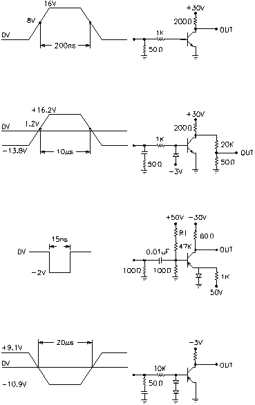
Fig. 11 Typical MIL-S-19500 test waveforms.
2) TRR and TFR (Methods 4031.1 and 4026.2 MIL-STD-750C).
The AVR-EB2A-B series was specifically designed to provide the diode switching time test waveforms specified in MIL-STD-750C, Methods 4031.1 and 4026.2 for TRR and TFR. Model AVR-EB2A-B generates two pulsed outputs (a positive turn-on waveform and a negative turn-off waveform) and in addition provides the necessary variable delay between the two outputs. A typical test arrangement for a 1N4150 TRR measurement is shown in Fig. 12 while a 1N4148 TFR test arrangement is shown in Fig. 13. Call 1-800-265-6681 for more detailed information.
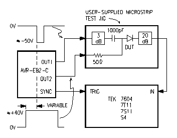
Fig. 12 1N4150 TRR, Method 4031.1 Test Condition B.
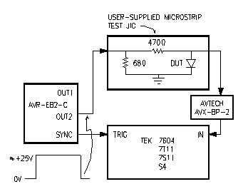
Fig. 13 1N4148, TFR Method 4026.2.
3) TRR and TL Tests For High-Speed Rectifier Diodes (see application note 1A)
4) Microwave Diode TT and TL
A common test procedure for measuring the carrier lifetime of high-speed step recovery diodes is shown in Fig.14. Model AVR-E1-W-N-C (see page 30) is well suited to this particular application. Models AVMP-4-C-N (see page 23) and AVI-V-N-C (see page 32) are also well suited particularly for extremely short lifetime devices (since these two models provide rise time of 200 ps and 350 ps, respectively). The same pulse generators may also be used to perform the transition time testing described in Fig. 15.
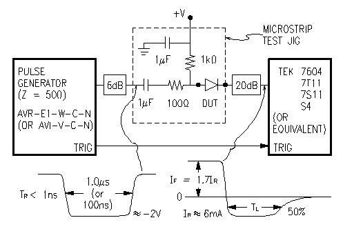
Fig. 14 Carrier lifetime test for high-speed step recovery diodes.
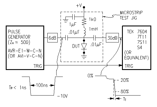
Fig. 15 Transition time test for high-speed step recovery diodes.

