Avtech products are no longer available (except for fulfillment of outstanding quotes). This price list is for reference only.
Effective 2025-04-15.
These prices are in U.S. dollars, and apply to orders placed directly with Avtech from the United States, Canada, and certain other countries. Local resellers may have different pricing. Click here for price list terms, shipping methods, warranty and repair information, and information about pricing for delivery to other countries.
Please see the bottom of this page for a summary of recent revisions. Recent price changes are noted with an asterisk.
OPTIONS COMMON TO ALL PRODUCT FAMILIESPULSE GENERATORS (AV-106 SERIES)
PULSE GENERATORS (AV-107 SERIES)
BROADBAND AMPLIFIERS (AV-110 SERIES)
BROADBAND AMPLIFIERS (AV-112 SERIES)
PULSE AMPLIFIERS (AV-140 SERIES)
HV LINEAR AMPLIFERS (AV-151 SERIES)
HV LINEAR AMPLIFERS (AV-153 SERIES)
PULSE GENERATORS (AV-156 SERIES)
PULSE GENERATORS (AV-1010 SERIES)
PULSE GENERATORS (AV-1020 SERIES)
PULSE GENERATORS (AV-1030 SERIES)
TRANSMISSION LINES (AV-CLZ AND AV-HLZ SERIES)
TRANSMISSION LINES (AV-LZ SERIES)
IMPULSE GENERATORS (AVG SERIES)
IMPULSE GENERATORS (AVH SERIES)
PULSE GENERATORS (AVI SERIES)
PULSE GENERATORS (AVIR SERIES)
PULSE GENERATORS (AVL SERIES)
IMPULSE GENERATORS (AVMH SERIES)
PULSE GENERATORS (AVMP SERIES)
PULSE GENERATORS (AVO-2 SERIES)
PULSE GENERATORS (AVO-6 SERIES)
PULSE GENERATORS (AVO-8 SERIES)
PULSE GENERATORS (AVO-9 SERIES)
PULSE GENERATORS (AVOZ-A, AVOZ-B, and AVOZ-G SERIES)
PULSE GENERATORS (AVOZ-D, AVOZ-E, and AVOZ-H SERIES)
PULSE GENERATORS (AVOZ-D and AVOZ-E SERIES)
PULSE GENERATORS (AVOZ-DF SERIES)
PULSE GENERATORS (AVP SERIES)
PULSE GENERATORS (AVPP SERIES)
PULSE GENERATORS (AVR SERIES)
PULSE GENERATORS (AVR-1, -2, -3 & -4)
PULSE GENERATORS (AVR-5, AVR-7, AVR-8)
PULSE GENERATORS (AVR-9 SERIES)
PULSE GENERATORS (AVR-CC SERIES)
PULSE GENERATORS (AVR-CD SERIES)
PULSE GENERATORS (AVR-D SERIES)
PULSE GENERATORS (AVR-DV SERIES)
PULSE GENERATORS (AVR-E SERIES)
PULSE GENERATORS (AVR-EB SERIES)
PULSE GENERATORS (AVRF SERIES)
PULSE GENERATORS (AVR-G SERIES)
PULSE GENERATORS (AVR-GHV SERIES)
PULSE GENERATORS (AVRH SERIES)
PULSE GENERATORS (AVRK SERIES)
PULSE GENERATORS (AVRQ SERIES)
PULSE GENERATORS (AVRZ-5 SERIES)
FREQUENCY DIVIDERS (AVX-FD SERIES)
LASER DIODE BIAS INSERTION UNITS (AVX-S)
ACCESSORIES
19" RACK MOUNT KIT
TEST LOADS
SHIPPING CASES
| OPTIONS COMMON TO ALL PRODUCT FAMILIES | ||
| Item | Price | Ordering Notes |
| -AC00, Power cord for United Kingdom, Hong Kong, Singapore, Malaysia | $X | BS 1363, 230V, 50 Hz. |
| -AC01, Power cord for Australia, New Zealand | $X | AS 3112:2000, 230-240V, 50 Hz. |
| -AC02, Power cord for Continental Europe, Korea, Indonesia, Russia | $X | CEE 7/7 Schuko, 230V, 50 Hz. |
| -AC03, Power cord for North America, Taiwan | $X | NEMA 5-15, 120V, 60 Hz. |
| -AC06, Power cord for Switzerland | $X | SEV 1011, 230V, 50 Hz. |
| -AC17, Power cord for South Africa, India | $X | SABS 164-1, 220-250V, 50 Hz. |
| -AC18, Power cord for Japan | $X | JIS 8303, 100V, 50-60 Hz. |
| -AC19, Power cord for Israel | $X | SI 32, 220V, 50 Hz. |
| -AC22, Power cord for China | $X | GB 1002-1, 220V, 50 Hz. |
| -ATA3, ATA shipping case | $XXXX | Ships the instrument in a heavy-duty ATA-style transport case, instead of the normal cardboard box. It can also serve as a storage case. This option is recommended for shipments outside of North America and Europe, and is mandatory when using a freight-forwarder or when shipping by any method other than FedEx/UPS. It is strongly recommended for all shipments to China. Pelican model 1690 for full-rack-width (17 inch / 430 mm) units, including all -B units. Pelican model 1610 for half-rack-width (8.5 inch / 215 mm) units. This option increases the shipping weight by 45 lbs / 20 kg (1690) or 24 lbs / 11 kg (1610). |
| -CC1, Provide a Certificate of Conformance | $XXX | |
| -ID1, Provide an installed IUID-format label | $XXX | Label only. Does not include data registration. Records the manufacturer CAGE code, the instrument serial number, and the model number. |
| -R5, Rack Mount Kit | $XXX | For 17-inch-wide models only. Check datasheet for instrument dimensions. (All -B units are 17 inches). |
| -VXI, Ethernet port, for remote control using VXI-11.3, ssh, telnet, and web | $X | Standard feature for orders after Jan 14, 2019 - it is no longer necessary to specify this option. Adds a rear-panel Ethernet connector, allowing the instrument to be remotely controlled using the VXI-11.3, ssh (secure shell), telnet, and http (web) protocols. In particular, the VXI-11.3 features allows software like LabView to control an instrument using standard VISA communications drivers and network cabling, instead of using old-style GPIB cabling. (This eliminates the need for a GPIB controller card and its proprietary drivers.) |
| -X1, Extra GPIB cable, 1 meter | $XX | |
| -X2, Extra GPIB cable, 2 meters | $XX | |
| -X4, Extra GPIB cable, 4 meters | $XX | |
| PULSE GENERATORS (AV-106 SERIES) | ||
| Item | Price | Ordering Notes |
| AV-106A-B, Current Pulser or Laser Diode Driver | $XXXXX | |
| AV-106B-B, Current Pulser or Laser Diode Driver | $XXXXX | |
| AV-106C-B, Current Pulser or Laser Diode Driver | $XXXXX | |
| AV-106D-B, Current Pulser or Laser Diode Driver | $XXXXX | |
| AV-106F-B, Current Pulser or Laser Diode Driver | $XXXXX | |
| -L200, 2m output cable instead of 1m | $XXX | |
| -PN, Dual polarity | $XXXX | |
| PULSE GENERATORS (AV-107 SERIES) | ||
| Item | Price | Ordering Notes |
| AV-107C-B, Current Pulser or Laser Diode Driver | $XXXXX | |
| AV-107D-B, Current Pulser or Laser Diode Driver | $XXXXX | |
| AV-107E-B, Current Pulser or Laser Diode Driver | $XXXXX | |
| -PN, Dual polarity | $XXXX | |
| -PW1, Extended maximum pulse width (20 us) | $XXXX | For AV-107C-B only. |
| BROADBAND AMPLIFIERS (AV-110 SERIES) | ||
| Item | Price | Ordering Notes |
| AV-110A-PS, High Voltage Amplifier | $XXXX | |
| AV-110B-PS, High Voltage Amplifier | $XXXX | |
| AV-110C-PS, High Voltage Amplifier | $XXXX | |
| AV-110D-PS, High Voltage Amplifier | $XXXX | |
| AV-110E-PS, High Voltage Amplifier | $XXXX | |
| AV-110G-PS, High Voltage Amplifier | $XXXX | |
| AV-110H-PS, High Voltage Amplifier | $XXXX | |
| AV-110J-PS, High Voltage Amplifier | $XXXX | |
| -D, Dual channel option | $XXXX | Excludes the AV-110A-PS, AV-110D-PS and AV-110J-PS |
| -D, Dual channel option | $XXXX | For AV-110A-PS, AV-110D-PS, and AV-110J-PS only. |
| -INV, Switchable inverting / non-inverting modes | $XXXX | Adds an inverting mode, in addition to the standard non-inverting mode. |
| -OS, Regular offset option | $XXX | |
| -XOS, Extended offset range | $XXXX | |
| BROADBAND AMPLIFIERS (AV-112 SERIES) | ||
| Item | Price | Ordering Notes |
| AV-112AH-PS, High Voltage Amplifier | $XXXXX | |
| AV-112A-PS, High Voltage Amplifier | $XXXX | |
| AV-112B-PS, High Voltage Amplifier | $XXXXX | |
| AV-112C-PS, High Voltage Amplifier | $XXXXX | |
| AV-112D-PS, High Voltage Amplifier | $XXXXX | |
| -INV, Switchable inverting / non-inverting modes | $XXXX | Adds an inverting mode, in addition to the standard non-inverting mode. |
| -OS, DC offset option | $XXXX | |
| PULSE AMPLIFIERS (AV-140 SERIES) | ||
| Item | Price | Ordering Notes |
| AV-141C1, DC-Coupled Pulse Amplifier | $XXXX | |
| AV-141C1-PS, DC-Coupled Pulse Amplifier | $XXXX | |
| AV-141G, DC-Coupled Pulse Amplifier | $XXXX | |
| AV-141G-PS, DC-Coupled Pulse Amplifier | $XXXX | |
| AV-141J, DC-Coupled Pulse Amplifier | $XXXX | |
| AV-141J-PS, DC-Coupled Pulse Amplifier | $XXXX | |
| AV-143B, DC-Coupled Pulse Amplifier | $XXXX | |
| AV-143B1, DC-Coupled Pulse Amplifier | $XXXX | |
| AV-143B1-PS, DC-Coupled Pulse Amplifier | $XXXX | |
| AV-143B-PS, DC-Coupled Pulse Amplifier | $XXXX | |
| AV-143CN, DC-Coupled Pulse Amplifier | $XXXX | |
| AV-143CN-PS, DC-Coupled Pulse Amplifier | $XXXX | |
| AV-143CP, DC-Coupled Pulse Amplifier | $XXXX | |
| AV-143CP-PS, DC-Coupled Pulse Amplifier | $XXXX | |
| AV-144C3-PS, Non-Linear Pulse Amplifier | $XXXX | |
| AV-144E1-PS, Non-Linear Pulse Amplifier | $XXXX | |
| -EA, Electronic amplitude control (analog) | $XXX | |
| -Z50, 50 Ohm input impedance | $X | Reduces the standard 1 kilohm input impedance. |
| HV LINEAR AMPLIFERS (AV-151 SERIES) | ||
| Item | Price | Ordering Notes |
| AV-151A-B, Function Generator | $XXXXX | |
| AV-151B-B, Function Generator | $XXXXX | |
| AV-151C-B, Function Generator | $XXXXX | |
| AV-151D-B, Function Generator | $XXXXX | |
| AV-151E-B, Function Generator | $XXXXX | |
| AV-151F-B, Function Generator | $XXXXX | |
| AV-151G-B, Function Generator | $XXXXX | |
| AV-151H-B, Function Generator | $XXXXX | |
| AV-151J-B, Function Generator | $XXXXX | |
| AV-151K-B, Function Generator | $XXXXX | |
| -PANB, Function generator burst mode, 1-500 cycles per trigger, pushbutton or computer command trigger will trigger burst | $XXXX | |
| -SIL, Safety Interlock | $XXX | This option adds a safety lock circuit on a rear-panel BNC connector. The signal pin of this safety lock BNC connector must be shorted to chassis ground by the user’s circuitry (the short must be capable of carrying 5 mA of current from an internal +5V/1kΩ DC source), otherwise the output will be switched off automatically. The connector shield is connected to chassis ground. |
| -XOS, Extended offset range | $XXXX | |
| HV LINEAR AMPLIFERS (AV-153 SERIES) | ||
| Item | Price | Ordering Notes |
| AV-153A-B, Function Generator | $XXXXX | |
| AV-153AH-B, Function Generator | $XXXXX | |
| AV-153B-B, Function Generator | $XXXXX | |
| AV-153C-B, Function Generator | $XXXXX | |
| -PANB, Function generator burst mode, 1-500 cycles per trigger, pushbutton or computer command trigger will trigger burst | $XXXX | |
| -SIL, Safety interlock | $XXX | This option adds a safety lock circuit on a rear-panel BNC connector. The signal pin of this safety lock BNC connector must be shorted to chassis ground by the user’s circuitry (the short must be capable of carrying 5 mA of current from an internal +5V/1kΩ DC source), otherwise the output will be switched off automatically. The connector shield is connected to chassis ground. |
| PULSE GENERATORS (AV-156 SERIES) | ||
| Item | Price | Ordering Notes |
| AV-156A-B, Current Pulser or Laser Diode Driver | $XXXXX | |
| AV-156E-B, Current Pulser or Laser Diode Driver | $XXXXX | |
| AV-156F-B, Current Pulser or Laser Diode Driver | $XXXXX | |
| AV-156G-B, Current Pulser or Laser Diode Driver | $XXXXX | |
| AV-156K-B, Current Pulser or Laser Diode Driver | $XXXXX | |
| AV-156L-B, Current Pulser or Laser Diode Driver | $XXXXX | |
| AV-156M-B, Current Pulser or Laser Diode Driver | $XXXXX | |
| -HC, Higher compliance voltage | $XXXX | |
| -PW, Extended pulse width range | $XXXX | |
| -R6, Rack Mount Kit | $XXX | For "3U" height instruments only. |
| -RP, Second output connector, on rear panel | $XXX | |
| PULSE GENERATORS (AV-1010 SERIES) | ||
| Item | Price | Ordering Notes |
| AV-1010-B, General Purpose Pulse Generator | $XXXXX | |
| AV-1011B1-B, General Purpose Pulse Generator | $XXXXX | |
| AV-1011B3-B, General Purpose Pulse Generator | $XXXXX | |
| AV-1011B5-B, General Purpose Pulse Generator | $XXXXX | |
| AV-1015-B, General Purpose Pulse Generator | $XXXXX | |
| -AK8, Accessory kit (adapters and short coaxial cables) | $XXX | Consists of one 12-inch SMA-M/SMA-M hand-formable coaxial cable with solderable jacket, one 12-inch SMA-M/SMA-M RG-316 coaxial cable, one 36-inch SMA-M/SMA-M RG-316 coaxial cable, one 24-inch SMA-M/BNC-M RG-316 coaxial cable, one 36-inch BNC-M/BNC-M RG58C/U coaxial cable, one SMA-F to BNC-M adapter, one SMA-M to BNC-F adapter, one SMA-F to SMA-F adapter, and one SMA-F to solder cup adapter. |
| PULSE GENERATORS (AV-1020 SERIES) | ||
| Item | Price | Ordering Notes |
| AV-1021-B, General Purpose Pulse Generator | $XXXXX | |
| AV-1023-C, General Purpose Pulse Generator | $XXXX | |
| AV-1041-B, General Purpose Pulse Generator | $XXXXX | |
| -TR, 5 ns rise time option | $XXXX | |
| PULSE GENERATORS (AV-1030 SERIES) | ||
| Item | Price | Ordering Notes |
| AV-1030-B, General Purpose Pulse Generator | $XXXXX | |
| -AK1, Accessory kit (attenuators and terminators) | $XXX | Consists of three SMA, 18 GHz, 2 Watt attenuators (10, 20 & 30 dB) and two 50 Ohm, 1 GHz, 1 Watt feed-through terminators (one SMA, one BNC) |
| -AK8, Accessory kit (adapters and short coaxial cables) | $XXX | Consists of one 12-inch SMA-M/SMA-M hand-formable coaxial cable with solderable jacket, one 12-inch SMA-M/SMA-M RG-316 coaxial cable, one 36-inch SMA-M/SMA-M RG-316 coaxial cable, one 24-inch SMA-M/BNC-M RG-316 coaxial cable, one 36-inch BNC-M/BNC-M RG58C/U coaxial cable, one SMA-F to BNC-M adapter, one SMA-M to BNC-F adapter, one SMA-F to SMA-F adapter, and one SMA-F to solder cup adapter. |
| TRANSMISSION LINES (AV-CLZ AND AV-HLZ SERIES) | ||
| Item | Price | Ordering Notes |
| AV-CLZ1, Low Impedance Transmission Line | $XXXX | |
| AV-CLZ11, Low Impedance Transmission Line | $XXX | |
| AV-CLZ2, Low Impedance Transmission Line | $XXX | |
| AV-CLZ3, Low Impedance Transmission Line | $XXX | |
| AV-CLZ4, Low Impedance Transmission Line | $XXX | |
| AV-CLZ5, Low Impedance Transmission Line | $XXX | |
| AV-HLZ1, Low Impedance Transmission Line | $XXXX | |
| AV-HLZ2, Low Impedance Transmission Line | $XXXX | |
| AV-HLZAX, Test Load / Adapter | $XXX | |
| -060, 60 cm length | $X | For CLZ series |
| -100, 1m length | $XXX | For CLZ series |
| -100, 1m length | $X | For HLZ series |
| -200, 2m length | $XXX | For CLZ1 and HLZ1 |
| -200, 2m length | $XXX | Excludes CLZ1 and HLZ1 |
| TRANSMISSION LINES (AV-LZ SERIES) | ||
| Item | Price | Ordering Notes |
| AV-LZ1, Low Impedance Transmission Line | $XXX | |
| AV-LZ10, Low Impedance Transmission Line | $XXX | |
| AV-LZ12, Low Impedance Transmission Line | $XXX | |
| AV-LZ2, Low Impedance Transmission Line | $XXX | |
| AV-LZ3, Low Impedance Transmission Line | $XXX | |
| AV-LZ6, Low Impedance Transmission Line | $XXX | |
| -2M, Extended length (2 meters total) | $XXX | |
| -3M, Extended length (3 meters total) | $XXX | |
| -BNC, Connectorize input end with a BNC male connector. | $XXX | |
| -DB37M, Connectorize input end with a DB-37 male connector. | $XXX | |
| -EDAC, Connectorize input end with an EDAC connector (for use with older Avtech pulsers) | $X | When ordering, please specify the model and serial number of the Avtech mainframe that will be used with the cable, to confirm compatibility |
| IMPULSE GENERATORS (AVG SERIES) | ||
| Item | Price | Ordering Notes |
| AVG-1-B, Impulse Generator | $XXXXX | |
| AVG-2-B, Impulse Generator | $XXXXX | |
| AVG-3A-B, Impulse Generator | $XXXXX | |
| AVG-3-B, Impulse Generator | $XXXXX | |
| AVG-3B-B, Impulse Generator | $XXXXX | |
| AVG-4A-B, Impulse Generator | $XXXXX | |
| AVG-4B2-B, Impulse Generator | $XXXXX | |
| AVG-4C2-B, Impulse Generator | $XXXXX | |
| -AK2, Accessory kit (attenuators and terminators) | $XXX | Consists of one SMA 12 GHz 20 Watt attenuator (20 dB) and two SMA 18 GHz 2 Watt attenuators (10 & 20 dB) for use on the output, and two 50 Ohm, 1 GHz, 1 Watt feed-through terminators (one SMA, one BNC) for use on external trigger inputs. |
| -AK8, Accessory kit (adapters and short coaxial cables) | $XXX | Consists of one 12-inch SMA-M/SMA-M hand-formable coaxial cable with solderable jacket, one 12-inch SMA-M/SMA-M RG-316 coaxial cable, one 36-inch SMA-M/SMA-M RG-316 coaxial cable, one 24-inch SMA-M/BNC-M RG-316 coaxial cable, one 36-inch BNC-M/BNC-M RG58C/U coaxial cable, one SMA-F to BNC-M adapter, one SMA-M to BNC-F adapter, one SMA-F to SMA-F adapter, and one SMA-F to solder cup adapter. |
| -M, Monitor output | $XXX | The monitor output provides an attenuated replica of the voltage on the main output, for largely non-invasive waveform measurements. |
| -OS, Bias tee circuit for externally-generated DC offset | $XXX | |
| -PN, Dual polarity | $XXXX | |
| IMPULSE GENERATORS (AVH SERIES) | ||
| Item | Price | Ordering Notes |
| AVH-B, Impulse Generator | $XXXXX | |
| AVH-C, Impulse Generator | $XXXX | |
| AVH-HV1-B, Impulse Generator | $XXXXX | |
| AVH-HV1-C, Impulse Generator | $XXXX | |
| AVH-S-B, Impulse Generator | $XXXXX | |
| AVH-SB-B, Impulse Generator | $XXXXX | |
| AVH-SB-C, Impulse Generator | $XXXX | |
| AVH-S-C, Impulse Generator | $XXXX | |
| -AK1, Accessory kit (attenuators and terminators) | $XXX | Consists of three SMA, 18 GHz, 2 Watt attenuators (10, 20 & 30 dB) and two 50 Ohm, 1 GHz, 1 Watt feed-through terminators (one SMA, one BNC) |
| -AK2, Accessory kit (attenuators and terminators) | $XXX | Consists of one SMA 12 GHz 20 Watt attenuator (20 dB) and two SMA 18 GHz 2 Watt attenuators (10 & 20 dB) for use on the output, and two 50 Ohm, 1 GHz, 1 Watt feed-through terminators (one SMA, one BNC) for use on external trigger inputs. |
| -AK8, Accessory kit (adapters and short coaxial cables) | $XXX | Consists of one 12-inch SMA-M/SMA-M hand-formable coaxial cable with solderable jacket, one 12-inch SMA-M/SMA-M RG-316 coaxial cable, one 36-inch SMA-M/SMA-M RG-316 coaxial cable, one 24-inch SMA-M/BNC-M RG-316 coaxial cable, one 36-inch BNC-M/BNC-M RG58C/U coaxial cable, one SMA-F to BNC-M adapter, one SMA-M to BNC-F adapter, one SMA-F to SMA-F adapter, and one SMA-F to solder cup adapter. |
| -OS, Bias tee circuit for externally-generated DC offset | $XXX | |
| -PN, Dual polarity | $XXXX | |
| -T1, 800ps pulse width option | $XXXX | |
| PULSE GENERATORS (AVI SERIES) | ||
| Item | Price | Ordering Notes |
| AVI-V-3L-B, Ultra High Speed Pulse Generator | $XXXXX | |
| AVI-V-B, Ultra High Speed Pulse Generator | $XXXXX | |
| AVI-V-HV2B-B, Ultra High Speed Pulse Generator | $XXXXX | |
| AVI-V-HV3A-B, Ultra High Speed Pulse Generator | $XXXXX | |
| -AK1, Accessory kit (attenuators and terminators) | $XXX | Consists of three SMA, 18 GHz, 2 Watt attenuators (10, 20 & 30 dB) and two 50 Ohm, 1 GHz, 1 Watt feed-through terminators (one SMA, one BNC) |
| -AK2, Accessory kit (attenuators and terminators) | $XXX | Consists of one SMA 12 GHz 20 Watt attenuator (20 dB) and two SMA 18 GHz 2 Watt attenuators (10 & 20 dB) for use on the output, and two 50 Ohm, 1 GHz, 1 Watt feed-through terminators (one SMA, one BNC) for use on external trigger inputs. |
| -AK8, Accessory kit (adapters and short coaxial cables) | $XXX | Consists of one 12-inch SMA-M/SMA-M hand-formable coaxial cable with solderable jacket, one 12-inch SMA-M/SMA-M RG-316 coaxial cable, one 36-inch SMA-M/SMA-M RG-316 coaxial cable, one 24-inch SMA-M/BNC-M RG-316 coaxial cable, one 36-inch BNC-M/BNC-M RG58C/U coaxial cable, one SMA-F to BNC-M adapter, one SMA-M to BNC-F adapter, one SMA-F to SMA-F adapter, and one SMA-F to solder cup adapter. |
| -M, Monitor output | $XXX | The monitor output provides an attenuated replica of the voltage on the main output, for largely non-invasive waveform measurements. |
| -OS, Bias tee circuit for externally-generated DC offset | $XXX | |
| -OT, Bias tee circuit for internally or externally generated DC offset | $XXXX | |
| -PN, Dual polarity | $XXXX | |
| PULSE GENERATORS (AVIR SERIES) | ||
| Item | Price | Ordering Notes |
| AVIR-1-B, High Voltage Pulser | $XXXXX | |
| AVIR-2-B, High Voltage Pulser | $XXXXX | |
| AVIR-3-B, High Voltage Pulser | $XXXXX | |
| AVIR-4-B, High Voltage Pulser | $XXXXX | |
| AVIR-4D-B, High Voltage Pulser | $XXXXX | |
| -EA, Electronic amplitude control (analog) | $XXXX | |
| -M, Monitor output | $XXX | The monitor output provides an attenuated replica of the voltage on the main output, for largely non-invasive waveform measurements. |
| -OS, Bias tee circuit for externally-generated DC offset | $XXX | |
| -OT, Bias tee circuit for internally or externally generated DC offset | $XXXX | |
| -PN, Dual polarity | $XXXX | |
| -PN, Dual polarity | $XXXX | For -1, -2 units only |
| PULSE GENERATORS (AVL SERIES) | ||
| Item | Price | Ordering Notes |
| AVL-2A-W-B, High Voltage Pulser | $XXXXX | |
| AVL-2D-B, High Voltage Pulser | $XXXXX | |
| AVL-5-B, High Voltage Pulser | $XXXXX | |
| AVL-AV-1-W-B, High Voltage Pulser | $XXXXX | |
| -DPF, Double pulse modes | $XXXX | |
| -M, Monitor output | $XXX | The monitor output provides an attenuated replica of the voltage on the main output, for largely non-invasive waveform measurements. |
| -OS, Bias tee circuit for externally-generated DC offset | $XXX | |
| -PN, Dual polarity | $XXXX | |
| -TR, 2.5 ns rise time option | $XXXX | |
| IMPULSE GENERATORS (AVMH SERIES) | ||
| Item | Price | Ordering Notes |
| AVMH-1A-C, Impulse Generator | $XXXX | |
| AVMH-1-C, Impulse Generator | $XXXX | |
| AVMH-2-C, Impulse Generator | $XXXX | |
| AVMH-3-C, Impulse Generator | $XXXX | |
| AVMH-4-C, Impulse Generator | $XXXXX | |
| AVMH-5-C, Impulse Generator | $XXXXX | |
| AVMH-6-C, Impulse Generator | $XXXXX | |
| -AK1, Accessory kit (attenuators and terminators) | $XXX | Consists of three SMA, 18 GHz, 2 Watt attenuators (10, 20 & 30 dB) and two 50 Ohm, 1 GHz, 1 Watt feed-through terminators (one SMA, one BNC) |
| -AK2, Accessory kit (attenuators and terminators) | $XXX | Consists of one SMA 12 GHz 20 Watt attenuator (20 dB) and two SMA 18 GHz 2 Watt attenuators (10 & 20 dB) for use on the output, and two 50 Ohm, 1 GHz, 1 Watt feed-through terminators (one SMA, one BNC) for use on external trigger inputs. |
| -AK8, Accessory kit (adapters and short coaxial cables) | $XXX | Consists of one 12-inch SMA-M/SMA-M hand-formable coaxial cable with solderable jacket, one 12-inch SMA-M/SMA-M RG-316 coaxial cable, one 36-inch SMA-M/SMA-M RG-316 coaxial cable, one 24-inch SMA-M/BNC-M RG-316 coaxial cable, one 36-inch BNC-M/BNC-M RG58C/U coaxial cable, one SMA-F to BNC-M adapter, one SMA-M to BNC-F adapter, one SMA-F to SMA-F adapter, and one SMA-F to solder cup adapter. |
| -M, Monitor output | $XXX | |
| -N-PN, Dual polarity (negative mainframe output) | $XXXX | |
| -OS, Bias tee circuit for externally-generated DC offset | $XXX | |
| -P-PN, Dual polarity (positive mainframe output) | $XXXX | |
| -Z1K, Greater than 1 kilohm external trigger input impedance | $X | |
| PULSE GENERATORS (AVMP SERIES) | ||
| Item | Price | Ordering Notes |
| AVMP-2A-B, Ultra High Speed Pulse Generator | $XXXXX | |
| AVMP-2-B, Ultra High Speed Pulse Generator | $XXXXX | |
| AVMP-3A-B, Ultra High Speed Pulse Generator | $XXXXX | |
| AVMP-3-B, Ultra High Speed Pulse Generator | $XXXXX | |
| AVMP-4-B, Ultra High Speed Pulse Generator | $XXXXX | |
| -AK1, Accessory kit (attenuators and terminators) | $XXX | Consists of three SMA, 18 GHz, 2 Watt attenuators (10, 20 & 30 dB) and two 50 Ohm, 1 GHz, 1 Watt feed-through terminators (one SMA, one BNC) |
| -AK8, Accessory kit (adapters and short coaxial cables) | $XXX | Consists of one 12-inch SMA-M/SMA-M hand-formable coaxial cable with solderable jacket, one 12-inch SMA-M/SMA-M RG-316 coaxial cable, one 36-inch SMA-M/SMA-M RG-316 coaxial cable, one 24-inch SMA-M/BNC-M RG-316 coaxial cable, one 36-inch BNC-M/BNC-M RG58C/U coaxial cable, one SMA-F to BNC-M adapter, one SMA-M to BNC-F adapter, one SMA-F to SMA-F adapter, and one SMA-F to solder cup adapter. |
| -ELA, Extends internally-generated DC offset range to +/-10V | $XXX | AVMP-3-B units only |
| -M, Monitor output | $XXX | The monitor output provides an attenuated replica of the voltage on the main output, for largely non-invasive waveform measurements. |
| -OS, Bias tee circuit for externally-generated DC offset | $XXX | For units with 100ns maximum PW (AVMP-2, AVMP-3). |
| -OS, Bias tee circuit for externally-generated DC offset | $XXXX | For units with 1us maximum PW (AVMP-2A, AVMP-3A). |
| -OT, Bias tee circuit for internally or externally generated DC offset | $XXXX | For units with 100ns maximum PW (AVMP-2, AVMP-3). |
| -OT, Bias tee circuit for internally or externally generated DC offset | $XXXX | For units with 1us maximum PW (AVMP-2A, AVMP-3A). |
| -PN, Dual polarity | $XXXX | |
| PULSE GENERATORS (AVO-2 SERIES) | ||
| Item | Price | Ordering Notes |
| AVO-2A-B, Laser Diode Driver (Pulsed Voltage) | $XXXXX | |
| AVO-2L-B, Laser Diode Driver (Pulsed Voltage) | $XXXXX | |
| AVO-2M-B, Laser Diode Driver (Pulsed Voltage) | $XXXXX | |
| AVO-2W-B, Laser Diode Driver (Pulsed Voltage) | $XXXXX | |
| -CLZ, Alternative output connector arrangement (CLZ style) | $XXXX | The output is provided on a DB-9 male connector, suitable for use with the Avtech AV-CLZ11 series of low impedance cables. Includes one AV-CLZ11-100 cable and one AV-CTLX DB-9-to-PCB adapter. The cable must be terminated by a user-supplied 11-13 Ohm resistance (or resistance in series with a diode). |
| -EA, Electronic amplitude control (analog) | $XXXX | |
| -M, Monitor output | $XXX | The monitor output provides an attenuated replica of the voltage on the main output, for largely non-invasive waveform measurements. |
| -OS, Bias tee circuit for externally-generated DC offset | $XXX | |
| -PN, Dual polarity | $XXXX | |
| -S3, Diode socket mounting option. | $XXXX | Customer must supply socket specifications. |
| PULSE GENERATORS (AVO-6 SERIES) | ||
| Item | Price | Ordering Notes |
| AVO-6A1-B, Laser Diode Driver (Pulsed Voltage) | $XXXXX | |
| AVO-6A-B, Laser Diode Driver (Pulsed Voltage) | $XXXXX | |
| AVO-6C1-B, Laser Diode Driver (Pulsed Voltage) | $XXXXX | |
| AVO-6C-B, Laser Diode Driver (Pulsed Voltage) | $XXXXX | |
| AVO-6D-B, Laser Diode Driver (Pulsed Voltage) | $XXXXX | |
| AVO-6F1-B, Laser Diode Driver (Pulsed Voltage) | $XXXXX | |
| AVO-6HF-B, Laser Diode Driver (Pulsed Voltage) | $XXXXX | |
| AVO-6HZ-B, Laser Diode Driver (Pulsed Voltage) | $XXXXX | |
| -CLZ, Alternative output connector arrangement (CLZ style) | $XXXX | The output is provided on a DB-9 male connector, suitable for use with the Avtech AV-CLZ11 series of low impedance cables. Includes one AV-CLZ11-100 cable and one AV-CTLX DB-9-to-PCB adapter. The cable must be terminated by a user-supplied 11-13 Ohm resistance (or resistance in series with a diode). |
| -M, Monitor output | $XXX | The monitor output provides an attenuated replica of the voltage on the main output, for largely non-invasive waveform measurements. |
| -OS, Bias tee circuit for externally-generated DC offset | $XXX | |
| -PN, Dual polarity | $XXXX | |
| -S, Diode socket mounting option | $XXXX | Customer must supply socket specifications. |
| -SMA, SMA output connector on output module | $XXX | Replaces the standard solder terminal outputs. |
| PULSE GENERATORS (AVO-8 SERIES) | ||
| Item | Price | Ordering Notes |
| -AK3, Recommended accessory kit (red/black cables and adapters) | $XXX | Red/Black cable kit for connection to the user-supplied DC power supply. |
| -AK9, Recommended accessory kit (AV-HLZ1-100 cable and cable-to-post adapter) | $XXXX | Recommended cable kit for the output. |
| -R6, Rack Mount Kit | $XXX | For "3U" height instruments only. |
| -TRIP, Current limit function | $XXX | |
| PULSE GENERATORS (AVO-9 SERIES) | ||
| Item | Price | Ordering Notes |
| AVO-9A3-B, Laser Diode Driver (Pulsed Voltage) | $XXXXX | |
| AVO-9A4-B, Laser Diode Driver (Pulsed Voltage) | $XXXXX | |
| AVO-9A-B, Laser Diode Driver (Pulsed Voltage) | $XXXXX | |
| AVO-9B1-B, Laser Diode Driver (Pulsed Voltage) | $XXXXX | |
| AVO-9B2-B, Laser Diode Driver (Pulsed Voltage) | $XXXXX | |
| AVO-9B-B, Laser Diode Driver (Pulsed Voltage) | $XXXXX | |
| AVO-9G-B, Laser Diode Driver (Pulsed Voltage) | $XXXXX | |
| AVO-9H1-B, Laser Diode Driver (Pulsed Voltage) | $XXXXX | |
| AVO-9H-B, Laser Diode Driver (Pulsed Voltage) | $XXXXX | |
| AVO-9L-B, Laser Diode Driver (Pulsed Voltage) | $XXXXX | |
| AVO-9M-B, Laser Diode Driver (Pulsed Voltage) | $XXXXX | |
| AVO-9P-B, Laser Diode Driver (Pulsed Voltage) | $XXXX | |
| AVO-9W-B, Laser Diode Driver (Pulsed Voltage) | $XXXXX | |
| AVO-9X-B, Laser Diode Driver (Pulsed Voltage) | $XXXXX | |
| AVO-9Y-B, Laser Diode Driver (Pulsed Voltage) | $XXXXX | |
| -AK1, Accessory kit (attenuators and terminators) | $XXX | Consists of three SMA, 18 GHz, 2 Watt attenuators (10, 20 & 30 dB) and two 50 Ohm, 1 GHz, 1 Watt feed-through terminators (one SMA, one BNC) |
| -AK11, Accessory kit (low-dB attenuators) | $XXX | Consists of four SMA, 18 GHz, 2 Watt attenuators (3, 6, 10, 20 dB) |
| -AK2, Accessory kit (attenuators and terminators) | $XXX | Consists of one SMA 12 GHz 20 Watt attenuator (20 dB) and two SMA 18 GHz 2 Watt attenuators (10 & 20 dB) for use on the output, and two 50 Ohm, 1 GHz, 1 Watt feed-through terminators (one SMA, one BNC) for use on external trigger inputs. |
| -AK8, Accessory kit (adapters and short coaxial cables) | $XXX | Consists of one 12-inch SMA-M/SMA-M hand-formable coaxial cable with solderable jacket, one 12-inch SMA-M/SMA-M RG-316 coaxial cable, one 36-inch SMA-M/SMA-M RG-316 coaxial cable, one 24-inch SMA-M/BNC-M RG-316 coaxial cable, one 36-inch BNC-M/BNC-M RG58C/U coaxial cable, one SMA-F to BNC-M adapter, one SMA-M to BNC-F adapter, one SMA-F to SMA-F adapter, and one SMA-F to solder cup adapter. |
| -AT, Ten turn amplitude control | $XX | Replaces the standard one-turn amplitude dial with a ten-turn dial. |
| -EA, Electronic amplitude control (analog) | $XXX | |
| -EW, Electronic PW control (analog) | $XXX | |
| -MD, Photodiode monitor | $XXX | |
| -P0, Socket for 3-pin 5.6mm or 9mm package with 2.54mm pin circle diameter (generic). | $X | Estimated price only. Contact Avtech with the package's mechanical drawings and pinout information. |
| -P0C, Socket for 2-pin 5.6mm or 9mm package with 2.54mm pin circle diameter. | $X | Specifies this common diode configuration: The socket will accept a 2-pin 5.6mm or 9mm package, with a 2.54mm pin spacing and pin diameters of 0.38-0.56 mm diameter (15-22 mils). The pulse signal will be applied to one pin. The other pin will be grounded. The diode parasitic resistance (dV/dI at lasing) must be < 5 Ohm. No additional drawings are required if this option is specified. |
| -P0D, Socket for 2-4 pin 5.6mm or 9mm package with 2.54mm pin circle diameter and 15-22 mil pins. | $X | Specifies this common diode configuration: The socket will accept a 2, 3 or 4 pin 5.6mm or 9mm package with a 2.54mm pin circle diameter. Four pin sockets are provided, which accept pins of 0.38-0.56 mm diameter (15-22 mils). A pulse signal will be applied to one pin socket. The other three pin sockets will be grounded. The diode parasitic resistance (dV/dI at lasing) must be < 5 Ohm. No additional drawings are required if this option is specified. |
| -P0E, Socket for 2-4 pin 5.6mm or 9mm package with 2.54mm pin circle diameter and 12-17 mil pins. | $X | Specifies this common diode configuration: The socket will accept a 2, 3 or 4 pin 5.6mm or 9mm package with a 2.54mm pin circle diameter. Four pin sockets are provided, which accept pins of 0.30-0.43 mm diameter (12-17 mils). The pulse signal will be applied to one pin socket. The other three pin sockets will be grounded. The diode parasitic resistance (dV/dI at lasing) must be < 5 Ohm. No additional drawings are required if this option is specified. |
| -P1, Socket for butterfly package (generic). | $XXX | Estimated price only. Contact Avtech with the package's mechanical drawings and pinout information. |
| -P1B, Primary socket for butterfly package pins 8-14 (high-bandwidth drive pins), specific layout | $XXX | Specifies this common diode configuration (typical of Lumics diodes, and others): The socket will accept pins 8-14 of a standard butterfly package with 0.5 mm wide pins. A positive pulse will be applied to the diode anode (pin 10). Pins 8-9 and 11-13 will be grounded. Pin 14 will be made accessible through a solder terminal. (If the -T1B option is also ordered, pin 14 will be made accessible through a DB-9 connector instead, suitable for mating to a third-party temperature controller.) Four mounting holes on a 8.9 x 26 mm grid will be provided, on a support plate 5.5 mm below the pins (for lower height packages, order a -SPC spacer option). The diode parasitic resistance (dV/dI at lasing) must be < 1 Ohm. No additional drawings are required if this option is specified. Typically ordered in combination with the -T1B option. Must be ordered with positive (-P) polarity. |
| -P1C, Primary socket for butterfly package pins 8-14 (high-bandwidth drive pins), specific layout | $XXX | Specifies this common diode configuration (typical of QPhotonics diodes, and others): The socket will accept pins 8-14 of a standard butterfly package with 0.5 mm wide pins. A negative pulse will be applied to the diode cathode (pin 12). Pins 8-11 and 13-14 will be grounded. Four mounting holes on a 8.9 x 26 mm grid will be provided, on a support plate 5.5 mm below the pins (for lower height packages, order a -SPC spacer option). The laser input impedance (dV/dI at lasing) must be 25 Ohms (+/- 5 Ohms). No additional drawings are required if this option is specified. Typically ordered in combination with the -T1C option. Must be ordered with negative (-N) polarity. |
| -P1CR0, Primary socket for butterfly package pins 8-14 (high-bandwidth drive pins), specific layout | $XXX | Specifies this common diode configuration (typical of some EM4 diodes, and others): The socket will accept pins 8-14 of a standard butterfly package with 0.5 mm wide pins. A negative pulse will be applied to the diode cathode (pin 12). Pins 8-11 and 13-14 will be grounded. Four mounting holes on a 8.9 x 26 mm grid will be provided, on a support plate 5.5 mm below the pins (for lower height packages, order a -SPC spacer option). The laser input impedance (dV/dI at lasing) must be less than 5 Ohms. No additional drawings are required if this option is specified. Typically ordered in combination with the -T1C option. Must be ordered with negative (-N) polarity. This is the same as the -P1C option, except that the diode has no internal 25 Ohm resistance. |
| -P2, Socket for 3-pin 5.6mm package with 2.0mm pin circle diameter (generic). | $X | Estimated price only. Contact Avtech with the package's mechanical drawings and pinout information. |
| -P2B, Socket for 3-pin 5.6mm package, with typical Nichia pinout / resistance. | $X | Estimated price only. This specifies a pinout and series resistance compatible with the Nichia NDHV310APC and similar Nichia laser diodes. A socket is provided that will accept 3-pin 5.6 mm packages. Click on the hyperlink for a pinout drawing. The laser anode is on pin 1, and the laser cathode is on pin 3 and is common to the photodiode cathode and the case. Access to pin 2 (the photodiode anode) is not provided. No additional drawings are required if this option is specified. The laser input impedance (dV/dI at lasing) must be 20 Ohms (+/- 5 Ohms). Note that the maximum output current may be reduced by the high forward voltage drop typical of Nichia diodes (if > 3V). |
| -P2C, Socket for 2-pin 5.6mm package with 2.0mm pin circle diameter. | $X | Specifies this common diode configuration: The socket will accept a 2-pin 5.6mm package, with a 2.0mm pin spacing and pin diameters of 0.38-0.56 mm diameter (15-22 mils). The pulse signal will be applied to one pin. The other pin will be grounded. The diode parasitic resistance (dV/dI at lasing) must be < 5 Ohm. No additional drawings are required if this option is specified. |
| -P2D, Socket for 2-4 pin 5.6mm package with 2.0mm pin circle diameter and 15-22 mil pins. | $X | Specifies this common diode configuration: The socket will accept a 2, 3 or 4 pin 5.6mm package with a 2.0mm pin circle diameter. Four pin sockets are provided, which accept pins of 0.38-0.56 mm diameter (15-22 mils). The pulse signal will be applied to one pin socket. The other three pin sockets will be grounded. The diode parasitic resistance (dV/dI at lasing) must be < 5 Ohm. No additional drawings are required if this option is specified. |
| -P2E, Socket for 2-4 pin 5.6mm package with 2.0mm pin circle diameter and 12-17 mil pins. | $X | Specifies this common diode configuration: The socket will accept a 2, 3 or 4 pin 5.6mm package with a 2.0mm pin circle diameter. Four pin sockets are provided, which accept pins of 0.30-0.43 mm diameter (12-17 mils). A pulse signal will be applied to one pin socket. The other three pin sockets will be grounded. The diode parasitic resistance (dV/dI at lasing) must be < 5 Ohm. No additional drawings are required if this option is specified. |
| -P3, Socket for 8-pin DIP package (generic). | $XXX | Estimated price only. Contact Avtech with the package's mechanical drawings and pinout information. |
| -P4, Socket for 14-pin DIL package (generic). | $XXXX | Estimated price only. Contact Avtech with the package's mechanical drawings and pinout information. |
| -P4B, Socket for 14-pin DIL package, specific layout. | $XXXX | Provides a socket pinout suitable for use with certain Qphotonics DIL laser diodes (and others). The signal will be applied to pin 5, the laser anode. All other pins (1-4, 6-14) will normally be grounded. No access is provided to the thermal control pins, unless the -T4B option is ordered. The laser input impedance (dV/dI at lasing) must be between 0 and 5 Ohms. |
| -P5, Socket for 2-pin package with 2.5mm lead spacing and 0.5mm square pins | $X | Estimated price only. Contact Avtech with the package's mechanical drawings and pinout information. |
| -P6, No output module or socket | $X | For connectorized DUTs with SMA or K input connector and 50 Ohm input impedance. The user must confirm that the pulser polarity is appropriate for the DUT. Not suitable for models that require a transformer ratio greater than 1. |
| -P7, Socket for 8-pin TO-99 package | $XXXX | The socket will accept 8-pin TO-99 packages. The signal will be applied to one pin. All other pins will be grounded. The diode parasitic resistance (dV/dI at lasing) must be < 5 Ohm. No additional drawings are required if this option is specified. |
| -P8A, Socket for 2-pin 5mm epoxy LED package with 2.5mm pin spacing, and 0.5-0.6mm square pins | $XXX | Specifies this common diode configuration: The socket will accept a 2-pin 5mm epoxy LED package with 2.5mm pin spacing, and 0.5-0.6mm square pins. One pin will be driven with the specified polarity, and one pin will be grounded. The diode parasitic resistance (dV/dI at lasing) must be < 1 Ohm. No additional drawings are required if this option is specified. |
| -PWT, Ten turn PW control | $XX | Replaces the standard one-turn pulse width dial with a ten-turn dial. |
| -SPC41, Butterfly spacer plate for 4.1mm height | $XXX | 1.4 mm thick spacer plate, for butterfly packages with pins 4.1mm above the package bottom (instead of 5.5 mm) |
| -SPC46, Butterfly spacer plate for 4.6mm height | $XXX | 0.9 mm thick spacer plate, for butterfly packages with pins 4.6mm above the package bottom (instead of 5.5 mm) |
| -T1B, Secondary slide-on socket for butterfly package pins 1-7 (low bandwidth thermal control pins) | $XXX | Adds a secondary (low-bandwidth) slide-on socket board for pins 1-7 of a butterfly package. A flexible cable connects the slide-on socket to the output module. A male DB-9 connector is provided on the output module, which provides access to the thermal control pins of the diode. DB-9 pin 2 connects to diode pin 2 (TH). DB-9 pin 3 connects to diode pin 5 (TH). DB-9 pin 4 connects to diode pin 1 (TEC+). DB-9 pin 5 connects to diode pin 14 (TEC-). The remaining DB-9 pins are unconnected. Pins 3, 4, 6, and 7 of the diode are grounded. Access to the photodiode, if present, is not provided. This option requires the -P1B option. This option is designed for compatibility with Thorlabs temperature controllers and Lumics laser diodes. It may be suitable for others as well. |
| -T1C, Secondary slide-on socket for butterfly package pins 1-7 (low bandwidth thermal control pins) | $XXX | Adds a secondary (low-bandwidth) slide-on socket board for pins 1-7 of a butterfly package. A flexible cable connects the slide-on socket to the output module. A male DB-9 connector is provided on the output module, which provides access to the thermal control pins of the diode. DB-9 pin 2 connects to diode pin 1 (TH). DB-9 pin 3 connects to diode pin 2 (TH). DB-9 pin 4 connects to diode pin 6 (TEC+). DB-9 pin 5 connects to diode pin 7 (TEC-). The remaining DB-9 pins are unconnected. Pins 4 and 5 of the diode are grounded. Pin 3 is unconnected. Access to the photodiode, if present, is not provided. This option requires the -P1C or -P1CR0 option. This option is designed for compatibility with Thorlabs temperature controllers and certain QPhotonics laser diodes. It may be suitable for others as well. |
| -T1D, Secondary slide-on socket for butterfly package pins 1-7 (low bandwidth thermal control pins) | $XXX | Adds a secondary (low-bandwidth) slide-on socket board for pins 1-7 of a butterfly package. A flexible cable connects the slide-on socket to the output module. A male DB-9 connector is provided on the output module, which provides access to the thermal control pins of the diode. DB-9 pin 2 connects to diode pin 3 (TH). DB-9 pin 3 connects to diode pin 4 (TH). DB-9 pin 4 connects to diode pin 1 (TEC+). DB-9 pin 5 connects to diode pin 14 (TEC-). The remaining DB-9 pins are unconnected. Pins 2, 5, 6, and 7 of the diode are grounded. Access to the photodiode, if present, is not provided. This option requires the -P1B option. This option is designed for compatibility with Thorlabs temperature controllers and InPhenix IPSAD1511 laser diodes. It may be suitable for others as well. (This is similar to the -T1B option, except DUT pins 3 and 4 are used for the thermistor, instead of 2 and 5.) |
| -T4B, Thermal control pin access for DIL package. | $XXXX | A male DB-9 connector is provided on the output module, which provides access to the thermal control pins of the DIL-package diode. DB-9 pin 2 connects to diode pin 11 (TH). DB-9 pin 3 connects to diode pin 12 (TH). DB-9 pin 4 connects to diode pin 1 (TEC+). DB-9 pin 5 connects to diode pin 14 (TEC-). The remaining DB-9 pins are unconnected. Pins 2-4 and 6-10 of the diode are grounded. Access to the photodiode, if present, is not provided. This option requires the -P4B option. This option is designed for compatibility with Thorlabs temperature controllers and Qphotonics laser diodes. It may be suitable for others as well. |
| -TO3, Socket for TO-3 package (generic). | $XXXX | Estimated price only, for an 8-pin TO3 package with 1.02mm pins on a 12.7mm pin circle diameter, spaced 40 degrees apart. Contact Avtech with the package's exact mechanical drawings and pinout information. |
| -TO66, Socket for TO-66 package (generic). | $XXXX | Estimated price only, for a 9-pin TO66 package with 0.75mm pins on a 8.26mm pin circle diameter, spaced 36 degrees apart. Contact Avtech with the package's exact mechanical drawings and pinout information. |
| -W1, Extended pulse width range, 1 - 200 ns | $XXXX | |
| -W4, Extended pulse width range | $XXXX | |
| PULSE GENERATORS (AVOZ-A, AVOZ-B, and AVOZ-G SERIES) | ||
| Item | Price | Ordering Notes |
| AVOZ-A1A-B, Laser Diode Driver (Pulsed Voltage) | $XXXXX | |
| AVOZ-A3-B, Laser Diode Driver (Pulsed Voltage) | $XXXXX | |
| AVOZ-A4-B, Laser Diode Driver (Pulsed Voltage) | $XXXXX | |
| AVOZ-B3-B, Laser Diode Driver (Pulsed Voltage) | $XXXXX | |
| AVOZ-B4-B, Laser Diode Driver (Pulsed Voltage) | $XXXXX | |
| AVOZ-G1-B, Laser Diode Driver (Pulsed Voltage) | $XXXXX | |
| AVOZ-G2-B, Laser Diode Driver (Pulsed Voltage) | $XXXXX | |
| AVOZ-G3-B, Laser Diode Driver (Pulsed Voltage) | $XXXXX | |
| -AK1, Accessory kit (attenuators and terminators) | $XXX | Consists of three SMA, 18 GHz, 2 Watt attenuators (10, 20 & 30 dB) and two 50 Ohm, 1 GHz, 1 Watt feed-through terminators (one SMA, one BNC) |
| -AK3, Recommended accessory kit (red/black cables and adapters) | $XXX | Red/Black cable kit for connection to the user-supplied DC power supply. |
| -AK8, Accessory kit (adapters and short coaxial cables) | $XXX | Consists of one 12-inch SMA-M/SMA-M hand-formable coaxial cable with solderable jacket, one 12-inch SMA-M/SMA-M RG-316 coaxial cable, one 36-inch SMA-M/SMA-M RG-316 coaxial cable, one 24-inch SMA-M/BNC-M RG-316 coaxial cable, one 36-inch BNC-M/BNC-M RG58C/U coaxial cable, one SMA-F to BNC-M adapter, one SMA-M to BNC-F adapter, one SMA-F to SMA-F adapter, and one SMA-F to solder cup adapter. |
| -EA, Electronic amplitude control (analog) | $XXX | |
| -PN, Dual polarity | $XXXX | |
| -R6, Rack Mount Kit | $XXX | For "3U" height instruments only. |
| PULSE GENERATORS (AVOZ-D, AVOZ-E, and AVOZ-H SERIES) | ||
| Item | Price | Ordering Notes |
| AVOZ-D1-B, Laser Diode Driver (Pulsed Voltage) | $XXXXX | |
| AVOZ-D2-B, Laser Diode Driver (Pulsed Voltage) | $XXXXX | |
| AVOZ-D3-B, Laser Diode Driver (Pulsed Voltage) | $XXXXX | |
| AVOZ-D4-B, Laser Diode Driver (Pulsed Voltage) | $XXXXX | |
| AVOZ-D5-B, Laser Diode Driver (Pulsed Voltage) | $XXXXX | |
| AVOZ-D6-B, Laser Diode Driver (Pulsed Voltage) | $XXXXX | |
| AVOZ-D7-B, Laser Diode Driver (Pulsed Voltage) | $XXXXX | |
| AVOZ-D9-B, Laser Diode Driver (Pulsed Voltage) | $XXXXX | |
| AVOZ-E1-B, Laser Diode Driver (Pulsed Voltage) | $XXXXX | |
| AVOZ-E2-B, Laser Diode Driver (Pulsed Voltage) | $XXXXX | |
| AVOZ-E3-B, Laser Diode Driver (Pulsed Voltage) | $XXXXX | |
| AVOZ-E4-B, Laser Diode Driver (Pulsed Voltage) | $XXXXX | |
| AVOZ-E5-B, Laser Diode Driver (Pulsed Voltage) | $XXXXX | |
| AVOZ-H1-B, Laser Diode Driver (Pulsed Voltage) | $XXXXX | |
| AVOZ-H2-B, Laser Diode Driver (Pulsed Voltage) | $XXXXX | |
| -BNC, BNC output connector | $XXX | Replaces the Type-N connector on the output module with a female BNC connector |
| -CK10, Cable kit (ten RG-58C/U cables, 5ft/152cm) | $XXX | |
| -CK20, Cable kit (twenty RG-58C/U cables, 5ft/152cm) | $XXXX | |
| -CK5, Cable kit (five RG-58C/U cables, 5ft/152cm) | $XXX | |
| -OM10, Output module (ten input connectors) | $XXXX | |
| -OM20, Output module (twenty input connectors) | $XXXX | |
| -OM5, Output module (five input connectors) | $XXX | |
| -PN, Dual polarity | $XXXX | |
| -XP2, Extra High Power | $XXXX | Not available on dual-polarity models, due to space limitations |
| PULSE GENERATORS (AVOZ-DF SERIES) | ||
| Item | Price | Ordering Notes |
| AVOZ-DF1-B, Laser Diode Driver (Pulsed Voltage) | $XXXXX | |
| AVOZ-DF2-B, Laser Diode Driver (Pulsed Voltage) | $XXXXX | |
| AVOZ-DF3-B, Laser Diode Driver (Pulsed Voltage) | $XXXXX | |
| AVOZ-DF5-B, Laser Diode Driver (Pulsed Voltage) | $XXXXX | |
| -XC3, Replace 1m/36"-long cables with 3m/118"-long cables | $XXX | |
| PULSE GENERATORS (AVP SERIES) | ||
| Item | Price | Ordering Notes |
| AVP-AV-1-B, Ultra High Speed Pulse Generator | $XXXXX | |
| AVP-AV-1S-C, Ultra High Speed Pulse Generator | $XXXXX | |
| AVP-AV-2-B, Ultra High Speed Pulse Generator | $XXXXX | |
| AVP-AV-HV2-B, Ultra High Speed Pulse Generator | $XXXXX | |
| AVP-AV-HV3-B, Ultra High Speed Pulse Generator | $XXXXX | |
| -AK1, Accessory kit (attenuators and terminators) | $XXX | Consists of three SMA, 18 GHz, 2 Watt attenuators (10, 20 & 30 dB) and two 50 Ohm, 1 GHz, 1 Watt feed-through terminators (one SMA, one BNC) |
| -AK8, Accessory kit (adapters and short coaxial cables) | $XXX | Consists of one 12-inch SMA-M/SMA-M hand-formable coaxial cable with solderable jacket, one 12-inch SMA-M/SMA-M RG-316 coaxial cable, one 36-inch SMA-M/SMA-M RG-316 coaxial cable, one 24-inch SMA-M/BNC-M RG-316 coaxial cable, one 36-inch BNC-M/BNC-M RG58C/U coaxial cable, one SMA-F to BNC-M adapter, one SMA-M to BNC-F adapter, one SMA-F to SMA-F adapter, and one SMA-F to solder cup adapter. |
| -AT, Ten turn amplitude control | $XX | Replaces the standard one-turn amplitude dial with a ten-turn dial. |
| -M, Monitor output | $XXX | The monitor output provides an attenuated replica of the voltage on the main output, for largely non-invasive waveform measurements. |
| -OS, Bias tee circuit for externally-generated DC offset | $XXX | |
| -OT, Bias tee circuit for internally or externally generated DC offset | $XXXX | |
| -PN, Dual polarity | $XXXX | |
| -W4, Wide pulse option (0.4-4 ns) | $XXXX | For AVP-AV-HV3 models only |
| -W5, Wide pulse option (0.3-4 ns) | $XXXX | For AVP-AV-HV2 models only |
| PULSE GENERATORS (AVPP SERIES) | ||
| Item | Price | Ordering Notes |
| AVPP-1A-B, Ultra High Speed Pulse Generator | $XXXXX | |
| AVPP-1-B, Ultra High Speed Pulse Generator | $XXXXX | |
| AVPP-2A-B, Ultra High Speed Pulse Generator | $XXXXX | |
| AVPP-2-B, Ultra High Speed Pulse Generator | $XXXXX | |
| -AK1, Accessory kit (attenuators and terminators) | $XXX | Consists of three SMA, 18 GHz, 2 Watt attenuators (10, 20 & 30 dB) and two 50 Ohm, 1 GHz, 1 Watt feed-through terminators (one SMA, one BNC) |
| -AK8, Accessory kit (adapters and short coaxial cables) | $XXX | Consists of one 12-inch SMA-M/SMA-M hand-formable coaxial cable with solderable jacket, one 12-inch SMA-M/SMA-M RG-316 coaxial cable, one 36-inch SMA-M/SMA-M RG-316 coaxial cable, one 24-inch SMA-M/BNC-M RG-316 coaxial cable, one 36-inch BNC-M/BNC-M RG58C/U coaxial cable, one SMA-F to BNC-M adapter, one SMA-M to BNC-F adapter, one SMA-F to SMA-F adapter, and one SMA-F to solder cup adapter. |
| -M, Monitor output | $XXXX | The monitor output provides an attenuated replica of the voltage on the main output, for largely non-invasive waveform measurements. |
| -OS, Bias tee circuit for externally-generated DC offset | $XXXX | For units with 1us maximum PW (AVPP-1A, AVPP-2A). |
| -OS, Bias tee circuit for externally-generated DC offset | $XXX | For units with 100ns maximum PW (AVPP-1, AVPP-2). |
| -OT, Bias tee circuit for internally or externally generated DC offset | $XXXX | For units with 100ns maximum PW (AVPP-1, AVPP-2). |
| -OT, Bias tee circuit for internally or externally generated DC offset | $XXXX | For units with 1us maximum PW (AVPP-1A, AVPP-2A). |
| -PN, Dual polarity | $XXXX | |
| PULSE GENERATORS (AVR SERIES) | ||
| Item | Price | Ordering Notes |
| AVR-A-1-PW-B, High Voltage Pulser | $XXXXX | |
| AVR-A-1-PW-C, High Voltage Pulser | $XXXX | |
| AVR-A-1-S2-C, High Voltage Pulser | $XXXX | |
| AVR-AHF-1-B, High Voltage Pulser | $XXXXX | |
| AVR-S3-B, High Voltage Pulser | $XXXXX | |
| -AT, Ten turn amplitude control | $XX | Replaces the standard one-turn amplitude dial with a ten-turn dial. |
| -EA, Electronic amplitude control (analog) | $XXX | |
| -OS, Bias tee circuit for externally-generated DC offset | $XXX | |
| -PN, Dual polarity | $XXXX | |
| -PWT, Ten turn PW control | $XX | Replaces the standard one-turn pulse width dial with a ten-turn dial. |
| PULSE GENERATORS (AVR-1, -2, -3 & -4) | ||
| Item | Price | Ordering Notes |
| AVR-1A-B, High Voltage Pulser | $XXXXX | |
| AVR-2A-B, High Voltage Pulser | $XXXXX | |
| AVR-2B-B, High Voltage Pulser | $XXXXX | |
| AVR-3-B, High Voltage Pulser | $XXXXX | |
| AVR-3HE-B, High Voltage Pulser | $XXXXX | |
| AVR-3HF-B, High Voltage Pulser | $XXXXX | |
| AVR-3HG-B, High Voltage Pulser | $XXXXX | |
| AVR-3-PW-TEK2-B, High Voltage Pulser | $XXXXX | The newer AVR-3-PW-TEK2-B and AVR-3-PW-TEK3-B models are recommended as enhanced replacements for the AVR-3-PW-TEK2-C model. |
| AVR-3-PW-TEK3-B, High Voltage Pulser | $XXXXX | The newer AVR-3-PW-TEK2-B and AVR-3-PW-TEK3-B models are recommended as enhanced replacements for the AVR-3-PW-TEK2-C model. |
| AVR-4-B, High Voltage Pulser | $XXXXX | |
| AVX-TEK2-SB1, Accessory | $XXX | |
| -CT, Additional output module, suitable for use with CT-1 or CT-2 current probes | $XXXX | |
| -LV, Switchable output impedance and internal attenuators | $XXXX | Adds a Zout = 50 Ohm mode (with reduced maximum average output power and duty cycle ratings in this mode). See datasheet for details. |
| -PN, Dual polarity | $XXXX | |
| -XP1, High Power | $XXXX | |
| -XP2, Extra High Power | $XXXX | Not available on dual-polarity models, due to space limitations |
| PULSE GENERATORS (AVR-5, AVR-7, AVR-8) | ||
| Item | Price | Ordering Notes |
| AVR-5B-B, High Voltage Pulser | $XXXXX | |
| AVR-7B-B, High Voltage Pulser | $XXXXX | |
| AVR-8A-B, High Voltage Pulser | $XXXXX | |
| -ADPT1, Adapter Kit | $XXX | Adapter kit, consisting of one SHV PLUG to MHV FEMALE adapter, and one MHV MALE to BNC FEMALE adapter. |
| -ADPT2, Adapter Kit | $XXX | N-male to BNC-female adapter (Amphenol P/N 31-216) |
| -HN, HN output connector | $XXX | Replaces standard output connector |
| -MHV, MHV output connector | $XXX | Replaces standard output connector |
| -NC, N output connector | $XXX | Replaces standard output connector |
| -PN, Dual polarity | $XXXX | |
| -QD, Quick-discharge circuit for higher throughput | $XXXX | |
| -R50, Switchable output impedance (0/50 Ohms) | $XXXX | |
| -SHV, SHV output connector | $XXX | Replaces standard output connector |
| -SIL, Safety interlock | $XXX | This option adds a safety lock circuit on a rear-panel BNC connector. The signal pin of this safety lock BNC connector must be shorted to chassis ground by the user’s circuitry (the short must be capable of carrying 5 mA of current from an internal +5V/1kΩ DC source), otherwise the output will be switched off automatically. The connector shield is connected to chassis ground. |
| -XP1, High Power | $XXXX | |
| -XP2, Extra High Power | $XXXX | Not available on dual-polarity models, due to space limitations |
| PULSE GENERATORS (AVR-9 SERIES) | ||
| Item | Price | Ordering Notes |
| AVR-9A-B, Medium Voltage High Speed Pulser | $XXXXX | |
| AVR-9B-B, Medium Voltage High Speed Pulser | $XXXXX | |
| AVR-9C-B, Medium Voltage High Speed Pulser | $XXXXX | |
| AVR-9D-B, Medium Voltage High Speed Pulser | $XXXXX | |
| PULSE GENERATORS (AVR-CD SERIES) | ||
| Item | Price | Ordering Notes |
| -AANB, Axial no-bend test jig daughterboard | $XXX | |
| -DO4, DO-4 test jig daughterboard | $XXX | |
| -DO5, DO-5 test jig daughterboard | $XXX | |
| -SQMELF, MELF/SQMELF test jig daughterboard | $XXX | |
| PULSE GENERATORS (AVR-D SERIES) | ||
| Item | Price | Ordering Notes |
| AVR-D2-B, Semiconductor Test Pulser | $XXXXX | |
| AVR-D3-B, Semiconductor Test Pulser | $XXXXX | |
| AVR-D4-B, Semiconductor Test Pulser | $XXXXX | |
| AVX-D4, Test Jig Daughterboard | $XXX | For use with the AVR-D4-B |
| -SOA, Extended amplitude range | $XXXX | Increases CH A maximum amplitude from 30V to 40V. |
| -TRF, Faster 1 ns CH A rise time | $XXXX | Not available with the -SOA option. |
| PULSE GENERATORS (AVR-DV SERIES) | ||
| Item | Price | Ordering Notes |
| AVR-DV1-B, Semiconductor Test Pulser | $XXXXX | |
| AVX-DVDT, dV/dt Test Jig | $XXXX | For use with the AVR-DV1-B |
| -EVC, Standard socket arrangement | $X | |
| -FTR, Faster rise time option | $XXXX | |
| -RTS, Rise time switch (required for use with AVR-DV1-B units with the -FTR option) | $XXX | |
| PULSE GENERATORS (AVR-E SERIES) | ||
| Item | Price | Ordering Notes |
| AVR-E1-B, Ultra High Speed Pulse Generator | $XXXXX | |
| AVR-E2A-B, High Voltage Pulser | $XXXXX | |
| AVR-E2-B, Ultra High Speed Pulse Generator | $XXXXX | |
| AVR-E3A-B, High Voltage Pulser | $XXXXX | |
| AVR-E3-B, Ultra High Speed Pulse Generator | $XXXXX | |
| -AK1, Accessory kit (attenuators and terminators) | $XXX | Consists of three SMA, 18 GHz, 2 Watt attenuators (10, 20 & 30 dB) and two 50 Ohm, 1 GHz, 1 Watt feed-through terminators (one SMA, one BNC) |
| -AK2, Accessory kit (attenuators and terminators) | $XXX | Consists of one SMA 12 GHz 20 Watt attenuator (20 dB) and two SMA 18 GHz 2 Watt attenuators (10 & 20 dB) for use on the output, and two 50 Ohm, 1 GHz, 1 Watt feed-through terminators (one SMA, one BNC) for use on external trigger inputs. |
| -AK8, Accessory kit (adapters and short coaxial cables) | $XXX | Consists of one 12-inch SMA-M/SMA-M hand-formable coaxial cable with solderable jacket, one 12-inch SMA-M/SMA-M RG-316 coaxial cable, one 36-inch SMA-M/SMA-M RG-316 coaxial cable, one 24-inch SMA-M/BNC-M RG-316 coaxial cable, one 36-inch BNC-M/BNC-M RG58C/U coaxial cable, one SMA-F to BNC-M adapter, one SMA-M to BNC-F adapter, one SMA-F to SMA-F adapter, and one SMA-F to solder cup adapter. |
| -OS, Bias tee circuit for externally-generated DC offset | $XXXX | For units with -W2 or -W3 options |
| -OS, Bias tee circuit for externally-generated DC offset | $XXX | For units without -W2 or -W3 options |
| -OT, Bias tee circuit for internally or externally generated DC offset | $XXXX | For units without -W2 or -W3 options |
| -OT, Bias tee circuit for internally or externally generated DC offset | $XXXX | For units with -W2 or -W3 options |
| -PN, Dual polarity | $XXXX | For units without -W2 or -W3 options |
| -PN, Dual polarity | $XXXX | For units with -W2 or -W3 options |
| -W1, Reduced minimum PW | $XXXX | |
| -W2, Increased maximum PW | $XXXX | |
| -W3, Reduced minimum PW and increased maximum PW | $XXXX | |
| PULSE GENERATORS (AVR-EB SERIES) | ||
| Item | Price | Ordering Notes |
| AVR-EB2A-B, Semiconductor Test Pulser | $XXXXX | Includes one AVX-CA-AXPOST test jig, unless otherwise specified. |
| AVR-EB2J-B, Semiconductor Test Pulser | $XXXXX | Includes one AVX-CA-AXPOST test jig, unless otherwise specified. |
| AVR-EB4-B, Semiconductor Test Pulser | $XXXXX | Includes one AVX-TRR-MIX test jig, unless otherwise specified. |
| AVR-EB5-B, Semiconductor Test Pulser | $XXXXX | Includes one AVX-TRR-MIX test jig, unless otherwise specified. |
| AVR-EB7-B, Semiconductor Test Pulser | $XXXXX | Includes one AVX-TRR-MIX test jig, unless otherwise specified. |
| AVR-EBF6-B, Semiconductor Test Pulser | $XXXXX | Includes one AVX-TFR-MIX test jig, unless otherwise specified. Also includes one AVX-FILT-10NS rise time filter. |
| AVX-CA, Reverse Recovery Test Jig | $XXXX | For use with the AVR-EB2A-B. Configured with -AXPOST option unless otherwise specified. |
| AVX-TFR, Forward Recovery Test Jig | $XXXX | For the AVR-EBF6-B forward recovery test systems. Configured with -MIX option unless otherwise specified. |
| AVX-TRR, Reverse Recovery Test Jig | $XXXX | For the AVR-EB4, -EB5, and -EB7 reverse recovery test systems. Configured with -MIX option unless otherwise specified. |
| -AXPOST, Axial no-bend test jig | $X | Suitable for low-to-medium current reverse recovery tests. Replaces earlier -ANB design. |
| -CK1, Extra cable kit for AVX-TRR jigs | $XXX | Cables are normally supplied with the pulse generator. This kit provides an extra set of cables, including: One 2m DB9 control cable, Two 60cm BNC-to-SMA coaxial cables, One 5m BNC-to-SMA coaxial cable. |
| -CK2, Extra cable kit for AVX-TFR jigs | $XXX | Cables are normally supplied with the pulse generator. This kit provides an extra set of cables, including: One 2m DB9 control cable, Three 60cm SMA-to-BNC coaxial cables, One 30 cm SMA-to-SMA coaxial cable. |
| -DO214AC, DO214AC test jig | $XXXX | Accepts DO214AC type SMT packages in a Loranger 03481 101 6218 socket. |
| -F12NS, 12 ns rise time filter accessory | $XXXX | This is in addition to the 10 ns rise time filter that is included as a standard feature. |
| -F20NS, 20 ns rise time filter accessory | $XXXX | This is in addition to the 10 ns rise time filter that is included as a standard feature. |
| -F8NS, 8 ns rise time filter accessory | $XXXX | This is in addition to the 10 ns rise time filter that is included as a standard feature. |
| -HPOST, High-current low-inductance axial test jig | $X | Suitable for low-to-high current reverse recovery tests, and forward recovery tests. Replaces earlier -ANB design. |
| -LORAX, Loranger socket for axial devices | $X | Uses a Loranger 03186 021 6215 socket for the DUT. Only suitable for reverse recovery tests due to relatively high inductance. |
| -MIX, MIX jig, with a variety of pin sockets | $X | Provides a mix of pin sockets to accept leaded devices. Leading bending required. |
| -SOD123, SOD123 test jig | $XXXX | Accepts SOD123 type SMT packages |
| -SOD123W, SOD123W jig | $XXXX | Accepts SOD123W type SMT packages |
| -SOD128, SOD128 test jig | $XXXX | Accepts SOD128 type SMT packages |
| -SQMELF, SQMELF jig | $XXXX | Accepts SQMELF packages. Replaces earlier -MELF design. |
| -STUD, Alternative stud jig | $XXXX | Accepts DO-4 and DO-5 stud packages. |
| -TO254AA, Alternative TO-254AA jig | $XXXX | Accepts TO254AA packages. |
| -UB, UB jig | $XXXX | Accepts MIL-STD UB packages. |
| -UMC, UMC jig | $XXXX | Accepts Semicoa UMC packages. |
| PULSE GENERATORS (AVRF SERIES) | ||
| Item | Price | Ordering Notes |
| AVRF-1-B, High Voltage Pulser | $XXXXX | |
| AVRF-2-B, High Voltage Pulser | $XXXXX | |
| AVRF-4A-B, High Voltage Pulser | $XXXXX | |
| AVRF-7B-B, High Voltage Pulser | $XXXXX | |
| -M, Monitor output | $XXX | The monitor output provides an attenuated replica of the voltage on the main output, for largely non-invasive waveform measurements. |
| -PN, Dual polarity | $XXXX | For -4A, -7B |
| -PN, Dual polarity | $XXXX | For -1, -2 |
| PULSE GENERATORS (AVR-G SERIES) | ||
| Item | Price | Ordering Notes |
| AVR-G1-B, High Voltage Pulser | $XXXXX | |
| AVR-G2-B, High Voltage Pulser | $XXXXX | |
| AVR-G4-B, High Voltage Pulser | $XXXXX | |
| AVR-G5-B, High Voltage Pulser | $XXXXX | |
| -OT, Internally generated offset option (0 to +/-50V) | $XXXX | |
| -PN, Dual polarity | $XXXX | |
| PULSE GENERATORS (AVR-GHV SERIES) | ||
| Item | Price | Ordering Notes |
| AVR-GHV1-B, High Voltage Pulser | $XXXXX | |
| AVR-GHV2-B, High Voltage Pulser | $XXXXX | |
| AVR-GHV4-B, High Voltage Pulser | $XXXXX | |
| AVR-GHV5-B, High Voltage Pulser | $XXXXX | |
| AVR-GHV6-B, High Voltage Pulser | $XXXXX | |
| -HN, HN output connector | $XXX | Replaces standard connector |
| -MHV, MHV output connector | $XXX | Replaces standard connector |
| -NC, N output connector | $XXX | Replaces standard connector |
| -PN, Dual polarity | $XXXX | |
| -SHV, SHV output connector | $XXX | Replaces standard connector |
| PULSE GENERATORS (AVRH SERIES) | ||
| Item | Price | Ordering Notes |
| AVRH-2-B, High Voltage Pulser | $XXXXX | |
| AVRH-3-B, High Voltage Pulser | $XXXXX | |
| -ADPT1, Adapter Kit | $XXX | Adapter kit, consisting of an SHV PLUG to MHV FEMALE adapter, and an MHV MALE to BNC FEMALE adapter. |
| -HN, HN output connector | $XXX | Replaces standard SHV connector |
| -MHV, MHV output connector | $XXX | Replaces standard SHV connector |
| -PN, Dual polarity | $XXXX | |
| PULSE GENERATORS (AVRK SERIES) | ||
| Item | Price | Ordering Notes |
| AVRK-1-B, High Voltage Pulser | $XXXXX | |
| AVRK-2-B, High Voltage Pulser | $XXXXX | |
| AVRK-3-B, High Voltage Pulser | $XXXXX | |
| AVRK-4-B, High Voltage Pulser | $XXXXX | |
| -DPF, Double pulse modes | $XXXX | |
| -LVA, Internally-switched high-power attenuator | $XXXX | For units without the -DPF option |
| -LVA, Internally-switched high-power attenuator | $XXXX | For units with the -DPF option |
| -OS, Bias tee circuit for externally-generated DC offset | $XXX | |
| -PN, Dual polarity | $XXXX | |
| -SIL, Safety interlock | $XXX | This option adds a safety lock circuit on a rear-panel BNC connector. The signal pin of this safety lock BNC connector must be shorted to chassis ground by the user’s circuitry (the short must be capable of carrying 5 mA of current from an internal +5V/1kΩ DC source), otherwise the output will be switched off automatically. The connector shield is connected to chassis ground. |
| -TR, Faster rise time option | $XXXX | |
| PULSE GENERATORS (AVRQ SERIES) | ||
| Item | Price | Ordering Notes |
| AVRQ-4-B, Semiconductor Test Pulser | $XXXXX | |
| AVRQ-5-B, Semiconductor Test Pulser | $XXXXX | |
| AVX-DB, Daughterboard Kit | $X | Special order code for custom daughterboards |
| -AHV, Finer Amplitude Control | $XXXX | + or -, 1.0 to 1.5 kV, in ≤ 1V steps. No change in rise time specification. |
| -DIP6, DIP6 daughterboards | $XXXX | Provides 32 additional unpopulated (bare) daughterboards (PCB 347A), suitable for use with certain DIP6 packages (with a 0.3" row spacing and 0.1" pin pitch). A socket may be used. The Vishay VOH1016AD is an example of a suitable DUT. Pin 5 is wired to GND2 and pin 6 is wired to VCC2. Pins 1-3 may be each configured to connect to VCC1 or GND1 through a chip resistor. Pin 4 is taken as the logic output. Refer to the design files for PCB 347A to verify device electrical and mechanical compatibility. Schematics and PCB layout files (in KiCad format) and Gerber/drill files are available for download from the Avtech web site, so that the user may produce additional daughterboards as required. |
| -DIP8, DIP8 daughterboards | $XXX | Provides 32 additional unpopulated (bare) standard daughterboards (PCB 267D), suitable for use with certain 0.3-inch DIP8 packages. (This is in addition to the eight assembled PCB 267D that are normally provided with AVRQ models.) Pin 5 is wired to GND2, and pin 8 is wired to VCC2. Pins 1-4 may be each configured to connect to VCC1 or GND1 through a chip resistor. Pin 6 or 7 may be taken as the logic output. Refer to the design files for PCB 267D to verify device electrical and mechanical compatibility. Schematics and PCB layout files (in KiCad format) and Gerber/drill files are available for download from the Avtech web site, so that the user may produce additional daughterboards as required. |
| -FPD, Front Panel DUT Area | $XXXX | Moves the DUT area (with hinged door) and HV PULSE connector from the rear panel to the front panel, for more convenient access. The overall height of the instrument is increased (from 3U to 5U in rack units) to accommodate the change. The DUT area is in the lower 3U, and the instrument controls are in the upper 2U. Must be ordered with the -ATA3 option for safe shipping. |
| -HF, Higher PRF | $XXX | Boosts maximum PRF from 10 Hz to 100 Hz |
| -LSOP6, LSOP6 daughterboards | $XXXX | Provides 32 additional unpopulated (bare) daughterboards (PCB P/N TBD), suitable for use with certain LSOP6 packages (with a nominal body size of 3.84x7.5mm, a 1.27mm pin pitch, and 10mm tip-to-tip lead spacing). Pin 4 is wired to GND2, and pin 6 is wired to VCC2. Pins 1-3 may be each configured to connect to VCC1 or GND1 through a chip resistor. Pin 5 is taken as the logic output. Refer to the design files for PCB P/N TBD to verify device electrical and mechanical compatibility. The user will need to solder the devices directly to the PCB, limiting the number of times that each PCB and device can be used. Schematics and PCB layout files (in KiCad format) and Gerber/drill files will be available for download from the Avtech web site, so that the user may produce additional daughterboards as required. |
| -R6, Rack Mount Kit | $XXX | For "3U" height instruments only. |
| -SCHB, Extended VCC2 Range | $XXX | Boosts the maximum VCC2 setting from +8V to +43V. |
| -SO16W, SO-16W daughterboards | $XXXX | Provides 32 additional unpopulated (bare) daughterboards (PCB 299C), suitable for use with certain SO-16W packages (refer to the design files for device compatibility). The user will need to solder the devices directly to the PCB, limiting the number of times that each PCB and device can be used. Schematics and PCB layout files (in KiCad format) and Gerber/drill files are available for download from the Avtech web site, so that the user may produce additional daughterboards as required. |
| -SO8, SO-8 daughterboards | $XXXX | Provides 32 additional unpopulated (bare) daughterboards (PCB 314B), suitable for use with certain SO-8 packages (with a nominal body size of 4x5mm, a 1.27mm pin pitch, and 6mm tip-to-tip lead spacing). Pin 5 is wired to GND2, and pin 8 is wired to VCC2. Pins 1-4 may be each configured to connect to VCC1 or GND1 through a chip resistor. Pin 6 or 7 may be taken as the logic output. Refer to the design files for PCB 314B to verify device electrical and mechanical compatibility. The user will need to solder the devices directly to the PCB, limiting the number of times that each PCB and device can be used. Schematics and PCB layout files (in KiCad format) and Gerber/drill files are available for download from the Avtech web site, so that the user may produce additional daughterboards as required. |
| -SOP5, SOP5 daughterboards | $XXXX | Provides 32 additional unpopulated (bare) daughterboards (PCB 298C), suitable for use with certain SOP5 packages (with a nominal body size of 4.55x4.1mm, a 1.27mm pin pitch, and 7mm tip-to-tip lead spacing). The Toshiba TLP2366 and Avago ACPL-M46U are examples of suitable DUTs. Pin 3 is wired to GND2, pin 5 is wired to VCC2, and pin 2 is wired to GND1. Pin 1 may be configured to connect to VCC1 or GND1 through a chip resistor. Pin 4 is taken as the logic output. Refer to the design files for PCB 298C to verify device electrical and mechanical compatibility. The user will need to solder the devices directly to the PCB, limiting the number of times that each PCB and device can be used. Schematics and PCB layout files (in KiCad format) and Gerber/drill files are available for download from the Avtech web site, so that the user may produce additional daughterboards as required. |
| -SOP6, SOP6 daughterboards | $XXXX | Provides 32 additional unpopulated (bare) daughterboards (PCB 348A), suitable for use with certain SOP6 packages (with a nominal body size of 4.6x6.8mm, a 1.27mm pin pitch, and 9.7mm tip-to-tip lead spacing). The Toshiba TLP702 is an example of a suitable DUT. Pin 4 is wired to GND2, and pin 6 is wired to VCC2. Pins 1-3 may be each configured to connect to VCC1 or GND1 through a chip resistor. Pin 5 is taken as the logic output. Refer to the design files for PCB 348A to verify device electrical and mechanical compatibility. The user will need to solder the devices directly to the PCB, limiting the number of times that each PCB and device can be used. Schematics and PCB layout files (in KiCad format) and Gerber/drill files are available for download from the Avtech web site, so that the user may produce additional daughterboards as required. |
| -SSO6, Stretched SO-6 daughterboards | $XXXX | Provides 32 additional unpopulated (bare) daughterboards (PCB P/N TBD), suitable for use with certain stretched SO-6 packages (see the Broadcom ACPL-W61L as an example). The user will need to solder the devices directly to the PCB, limiting the number of times that each PCB and device can be used. Schematics and PCB layout files (in KiCad format) and Gerber/drill files will be made available for download from the Avtech web site, so that the user may produce additional daughterboards as required. |
| -V2, VCC2 BNC Connector | $XXX | Adds a BNC connector on which VCC2 may be monitored (wired in parallel with the VCC2 connection on the DUT socket) |
| -XHV, Finer Extra-High Amplitude Control | $XXXX | + or -, 1.5 to 2.0 kV, in ≤ 1V steps. The minimum leading edge rise time increases by 5 ns. |
| PULSE GENERATORS (AVRZ-5 SERIES) | ||
| Item | Price | Ordering Notes |
| AVRZ-5W-B, High Voltage Pulser | $XXXXX | |
| -HN, HN output connector | $XXX | Replaces standard BNC connector |
| -INV, Polarity inverting transformer accessory | $XXXX | External accessory that allows generation of negative output amplitudes. Available separately as model AVX-R5. |
| -LVA, Internally-switched attenuators | $XXXX | Adds internally-switched attenuators to allow very low amplitude settings. The amplitude is adjustable from < 0.1V to 500V, in steps of < 0.1V. |
| -MHV, MHV output connector | $XXX | Replaces standard BNC connector |
| -NC, N output connector | $XXX | Replaces standard BNC connector |
| -OS, DC offset option | $XXXX | Also available separately as model AVX-TG |
| -PN, Dual polarity (internal control) | $XXXX | Allows generation of negative output amplitudes, without the use of external accessories. |
| -QD, Quick discharge | $X | Obsolete option suffix - this function is now included as a standard feature. |
| -SHV, SHV output connector | $XXX | Replaces standard BNC connector |
| -SIL, Safety interlock | $XXX | This option adds a safety lock circuit on a rear-panel BNC connector. The signal pin of this safety lock BNC connector must be shorted to chassis ground by the user’s circuitry (the short must be capable of carrying 5 mA of current from an internal +5V/1kΩ DC source), otherwise the output will be switched off automatically. The connector shield is connected to chassis ground. |
| FREQUENCY DIVIDERS (AVX-FD SERIES) | ||
| Item | Price | Ordering Notes |
| AVX-FD1-PS, Frequency Divider | $XXXX | |
| AVX-FD2-PS, Frequency Divider | $XXXX | |
| AVX-FD3-PS, Frequency Divider | $XXXX | |
| -EP, Complementary outputs | $XXX | |
| -IP, 0.2 to 5 Vpp analog input | $XXX | |
| -XN, Extended divisor range | $XXX | |
| LASER DIODE BIAS INSERTION UNITS (AVX-S) | ||
| Item | Price | Ordering Notes |
| AVX-S1, Laser Diode Bias Insertion Unit with Socket | $XXXX | |
| AVX-S2, Laser Diode Bias Insertion Unit with Socket | $XXXX | |
| AVX-S3A, Laser Diode Bias Insertion Unit with Socket | $XXXX | |
| AVX-S3C, Laser Diode Bias Insertion Unit with Socket | $XXXX | |
| AVX-S5, Laser Diode Bias Insertion Unit with Socket | $XXXX | |
| -AK1, Accessory kit (attenuators and terminators) | $XXX | Consists of three SMA, 18 GHz, 2 Watt attenuators (10, 20 & 30 dB) and two 50 Ohm, 1 GHz, 1 Watt feed-through terminators (one SMA, one BNC) |
| -AK11, Accessory kit (low-dB attenuators) | $XXX | Consists of four SMA, 18 GHz, 2 Watt attenuators (3, 6, 10, 20 dB) |
| -AK8, Accessory kit (adapters and short coaxial cables) | $XXX | Consists of one 12-inch SMA-M/SMA-M hand-formable coaxial cable with solderable jacket, one 12-inch SMA-M/SMA-M RG-316 coaxial cable, one 36-inch SMA-M/SMA-M RG-316 coaxial cable, one 24-inch SMA-M/BNC-M RG-316 coaxial cable, one 36-inch BNC-M/BNC-M RG58C/U coaxial cable, one SMA-F to BNC-M adapter, one SMA-M to BNC-F adapter, one SMA-F to SMA-F adapter, and one SMA-F to solder cup adapter. |
| -HP, Higher power DC bias resistor (5 Watts) | $XXX | |
| -INV, Polarity inverting option. | $XXX | |
| -MD, Photodiode monitor | $XXX | |
| -MI, Voltage monitor | $XXX | Standard feature on S1 and S2 models, optional on S3 models. |
| -MV, Voltage monitor | $XXX | Standard feature on S1 and S2 models, optional on S3 models. |
| -P0, Socket for 3-pin 5.6mm or 9mm package with 2.54mm pin circle diameter (generic). | $X | Estimated price only. Contact Avtech with the package's mechanical drawings and pinout information. |
| -P0C, Socket for 2-pin 5.6mm or 9mm package with 2.54mm pin circle diameter. | $X | Specifies this common diode configuration: The socket will accept a 2-pin 5.6mm or 9mm package, with a 2.54mm pin spacing and pin diameters of 0.38-0.56 mm diameter (15-22 mils). The positive pulse signal will be applied to the anode pin. The cathode pin will be grounded. The diode parasitic resistance (dV/dI at lasing) must be < 5 Ohm. No additional drawings are required if this option is specified. |
| -P0D, Socket for 2-4 pin 5.6mm or 9mm package with 2.54mm pin circle diameter and 15-22 mil pins. | $X | Specifies this common diode configuration: The socket will accept a 2, 3 or 4 pin 5.6mm or 9mm package with a 2.54mm pin circle diameter. Four pin sockets are provided, which accept pins of 0.38-0.56 mm diameter (15-22 mils). A pulse signal will be applied to one pin socket. The other three pin sockets will be grounded. The diode parasitic resistance (dV/dI at lasing) must be < 5 Ohm. No additional drawings are required if this option is specified. |
| -P0E, Socket for 2-4 pin 5.6mm or 9mm package with 2.54mm pin circle diameter and 12-17 mil pins. | $X | Specifies this common diode configuration: The socket will accept a 2, 3 or 4 pin 5.6mm or 9mm package with a 2.54mm pin circle diameter. Four pin sockets are provided, which accept pins of 0.30-0.43 mm diameter (12-17 mils). The pulse signal will be applied to one pin socket. The other three pin sockets will be grounded. The diode parasitic resistance (dV/dI at lasing) must be < 5 Ohm. No additional drawings are required if this option is specified. |
| -P1, Socket for butterfly package (generic). | $XXX | Estimated price only. Contact Avtech with the package's mechanical drawings and pinout information. |
| -P1B, Primary socket for butterfly package pins 8-14 (high-bandwidth drive pins), specific layout | $XXX | Specifies this common diode configuration (typical of Lumics diodes, and others): The socket will accept pins 8-14 of a standard butterfly package with 0.5 mm wide pins. A positive pulse will be applied to the diode anode (pin 10). Pins 8-9 and 11-13 will be grounded. Pin 14 will be made accessible through a solder terminal. (If the -T1B option is also ordered, pin 14 will be made accessible through a DB-9 connector instead, suitable for mating to a third-party temperature controller.) Four mounting holes on a 8.9 x 26 mm grid will be provided, on a support plate 5.5 mm below the pins (for lower height packages, order a -SPC spacer option). The diode parasitic resistance (dV/dI at lasing) must be < 1 Ohm. No additional drawings are required if this option is specified. Typically ordered in combination with the -T1B option. |
| -P1C, Primary socket for butterfly package pins 8-14 (high-bandwidth drive pins), specific layout | $XXX | Specifies this common diode configuration (typical of QPhotonics diodes, and others): The socket will accept pins 8-14 of a standard butterfly package with 0.5 mm wide pins. A negative pulse will be applied to the diode cathode (pin 12). Pins 8-11 and 13-14 will be grounded. Four mounting holes on a 8.9 x 26 mm grid will be provided, on a support plate 5.5 mm below the pins (for lower height packages, order a -SPC spacer option). The laser input impedance (dV/dI at lasing) must be 25 Ohms (+/- 5 Ohms). No additional drawings are required if this option is specified. Typically ordered in combination with the -T1C option. |
| -P1CR0, Primary socket for butterfly package pins 8-14 (high-bandwidth drive pins), specific layout | $XXX | Specifies this common diode configuration (typical of some EM4 diodes, and others): The socket will accept pins 8-14 of a standard butterfly package with 0.5 mm wide pins. A negative pulse will be applied to the diode cathode (pin 12). Pins 8-11 and 13-14 will be grounded. Four mounting holes on a 8.9 x 26 mm grid will be provided, on a support plate 5.5 mm below the pins (for lower height packages, order a -SPC spacer option). The laser input impedance (dV/dI at lasing) must be less than 5 Ohms. No additional drawings are required if this option is specified. Typically ordered in combination with the -T1C option. Must be ordered with negative (-N) polarity. This is the same as the -P1C option, except that the diode has no internal 25 Ohm resistance. |
| -P2, Socket for 3-pin 5.6mm package with 2.0mm pin circle diameter (generic). | $X | Estimated price only. Contact Avtech with the package's mechanical drawings and pinout information. |
| -P2B, Socket for 3-pin 5.6mm package, with typical Nichia pinout / resistance. | $X | Estimated price only. This specifies a pinout and series resistance compatible with the Nichia NDHV310APC and similar Nichia laser diodes. A socket is provided that will accept 3-pin 5.6 mm packages. Click on the hyperlink for a pinout drawing. The laser anode is on pin 1, and the laser cathode is on pin 3 and is common to the photodiode cathode and the case. Access to pin 2 (the photodiode anode) is not provided. No additional drawings are required if this option is specified. The laser input impedance (dV/dI at lasing) must be 20 Ohms (+/- 5 Ohms). Note that the maximum output current may be reduced by the high forward voltage drop typical of Nichia diodes (if > 3V). |
| -P2C, Socket for 2-pin 5.6mm package with 2.0mm pin circle diameter. | $X | Specifies this common diode configuration: The socket will accept a 2-pin 5.6mm package, with a 2.0mm pin spacing and pin diameters of 0.38-0.56 mm diameter (15-22 mils). The positive pulse signal will be applied to the anode pin. The cathode pin will be grounded. The diode parasitic resistance (dV/dI at lasing) must be < 5 Ohm. No additional drawings are required if this option is specified. |
| -P2D, Socket for 2-4 pin 5.6mm package with 2.0mm pin circle diameter and 15-22 mil pins. | $X | Specifies this common diode configuration: The socket will accept a 2, 3 or 4 pin 5.6mm package with a 2.0mm pin circle diameter. Four pin sockets are provided, which accept pins of 0.38-0.56 mm diameter (15-22 mils). A pulse signal will be applied to one pin socket. The other three pin sockets will be grounded. The diode parasitic resistance (dV/dI at lasing) must be < 5 Ohm. No additional drawings are required if this option is specified. |
| -P2E, Socket for 2-4 pin 5.6mm package with 2.0mm pin circle diameter and 12-17 mil pins. | $X | Specifies this common diode configuration: The socket will accept a 2, 3 or 4 pin 5.6mm package with a 2.0mm pin circle diameter. Four pin sockets are provided, which accept pins of 0.30-0.43 mm diameter (12-17 mils). A pulse signal will be applied to one pin socket. The other three pin sockets will be grounded. The diode parasitic resistance (dV/dI at lasing) must be < 5 Ohm. No additional drawings are required if this option is specified. |
| -P3, Socket for 8-pin DIP package (generic). | $XXX | Estimated price only. Contact Avtech with the package's mechanical drawings and pinout information. |
| -P4, Socket for 14-pin DIL package (generic). | $XXXX | Estimated price only. Contact Avtech with the package's mechanical drawings and pinout information. |
| -P4B, Socket for 14-pin DIL package, specific layout. | $XXXX | Provides a socket pinout suitable for use with certain Qphotonics DIL laser diodes (and others). The signal will be applied to pin 5, the laser anode. All other pins (1-4, 6-14) will normally be grounded. No access is provided to the thermal control pins, unless the -T4B option is ordered. The laser input impedance (dV/dI at lasing) must be between 0 and 5 Ohms. |
| -P5, Socket for 2-pin package with 2.5mm lead spacing and 0.5mm square pins | $X | Estimated price only. Contact Avtech with the package's mechanical drawings and pinout information. |
| -P7, Socket for 8-pin TO-99 package | $XXXX | The socket will accept 8-pin TO-99 packages. The signal will be applied to one pin. All other pins will be grounded. The diode parasitic resistance (dV/dI at lasing) must be < 5 Ohm. No additional drawings are required if this option is specified. |
| -P8A, Socket for 2-pin 5mm epoxy LED package with 2.5mm pin spacing, and 0.5-0.6mm square pins | $XXX | Specifies this common diode configuration: The socket will accept a 2-pin 5mm epoxy LED package with 2.5mm pin spacing, and 0.5-0.6mm square pins. One pin will be driven with the specified polarity, and one pin will be grounded. The diode parasitic resistance (dV/dI at lasing) must be < 1 Ohm. No additional drawings are required if this option is specified. |
| -SPC41, Butterfly spacer plate for 4.1mm height | $XXX | 1.4 mm thick spacer plate, for butterfly packages with pins 4.1mm above the package bottom (instead of 5.5 mm) |
| -SPC46, Butterfly spacer plate for 4.6mm height | $XXX | 0.9 mm thick spacer plate, for butterfly packages with pins 4.6mm above the package bottom (instead of 5.5 mm) |
| -T1B, Secondary slide-on socket for butterfly package pins 1-7 (low bandwidth thermal control pins) | $XXX | Adds a secondary (low-bandwidth) slide-on socket board for pins 1-7 of a butterfly package. A flexible cable connects the slide-on socket to the output module. A male DB-9 connector is provided on the output module, which provides access to the thermal control pins of the diode. DB-9 pin 2 connects to diode pin 2 (TH). DB-9 pin 3 connects to diode pin 5 (TH). DB-9 pin 4 connects to diode pin 1 (TEC+). DB-9 pin 5 connects to diode pin 14 (TEC-). The remaining DB-9 pins are unconnected. Pins 3, 4, 6, and 7 of the diode are grounded. Access to the photodiode, if present, is not provided. This option requires the -P1B option. This option is designed for compatibility with Thorlabs temperature controllers and Lumics laser diodes. It may be suitable for others as well. |
| -T1C, Secondary slide-on socket for butterfly package pins 1-7 (low bandwidth thermal control pins) | $XXX | Adds a secondary (low-bandwidth) slide-on socket board for pins 1-7 of a butterfly package. A flexible cable connects the slide-on socket to the output module. A male DB-9 connector is provided on the output module, which provides access to the thermal control pins of the diode. DB-9 pin 2 connects to diode pin 1 (TH). DB-9 pin 3 connects to diode pin 2 (TH). DB-9 pin 4 connects to diode pin 6 (TEC+). DB-9 pin 5 connects to diode pin 7 (TEC-). The remaining DB-9 pins are unconnected. Pins 4 and 5 of the diode are grounded. Pin 3 is unconnected. Access to the photodiode, if present, is not provided. This option requires the -P1C or -P1CR0 option. This option is designed for compatibility with Thorlabs temperature controllers and certain QPhotonics laser diodes. It may be suitable for others as well. |
| -T1D, Secondary slide-on socket for butterfly package pins 1-7 (low bandwidth thermal control pins) | $XXX | Adds a secondary (low-bandwidth) slide-on socket board for pins 1-7 of a butterfly package. A flexible cable connects the slide-on socket to the output module. A male DB-9 connector is provided on the output module, which provides access to the thermal control pins of the diode. DB-9 pin 2 connects to diode pin 3 (TH). DB-9 pin 3 connects to diode pin 4 (TH). DB-9 pin 4 connects to diode pin 1 (TEC+). DB-9 pin 5 connects to diode pin 14 (TEC-). The remaining DB-9 pins are unconnected. Pins 2, 5, 6, and 7 of the diode are grounded. Access to the photodiode, if present, is not provided. This option requires the -P1B option. This option is designed for compatibility with Thorlabs temperature controllers and InPhenix IPSAD1511 laser diodes. It may be suitable for others as well. (This is similar to the -T1B option, except DUT pins 3 and 4 are used for the thermistor, instead of 2 and 5.) |
| -T4B, Thermal control pin access for DIL package. | $XXXX | A male DB-9 connector is provided on the output module, which provides access to the thermal control pins of the DIL-package diode. DB-9 pin 2 connects to diode pin 11 (TH). DB-9 pin 3 connects to diode pin 12 (TH). DB-9 pin 4 connects to diode pin 1 (TEC+). DB-9 pin 5 connects to diode pin 14 (TEC-). The remaining DB-9 pins are unconnected. Pins 2-4 and 6-10 of the diode are grounded. Access to the photodiode, if present, is not provided. This option requires the -P4B option. This option is designed for compatibility with Thorlabs temperature controllers and Qphotonics laser diodes. It may be suitable for others as well. |
| -TO3, Socket for TO-3 package (generic). | $XXXX | Estimated price only, for an 8-pin TO3 package with 1.02mm pins on a 12.7mm pin circle diameter, spaced 40 degrees apart. Contact Avtech with the package's exact mechanical drawings and pinout information. |
| -TO66, Socket for TO-66 package (generic). | $XXXX | Estimated price only, for a 9-pin TO66 package with 0.75mm pins on a 8.26mm pin circle diameter, spaced 36 degrees apart. Contact Avtech with the package's exact mechanical drawings and pinout information. |
| ACCESSORIES | ||
| Item | Price | Ordering Notes |
| AV-ACC, Accessory | $X | |
| AVX-1, Pulse Transformer | $XXX | |
| AVX-1A, Pulse Transformer | $XXX | |
| AVX-1B, Pulse Transformer | $XXXX | |
| AVX-2, Pulse Transformer | $XXX | |
| AVX-3, Pulse Transformer | $XXX | |
| AVX-FILT, Rise Time Filter | $XXXX | |
| AVX-M4, Pulse Transformer | $XXX | |
| AVX-M4-H, Pulse Transformer | $XXXX | |
| AVX-MRA1, Pulse Transformer | $XXX | |
| AVX-MRA2, Pulse Transformer | $XXXX | |
| AVX-MRA4, Pulse Transformer | $XXXX | |
| AVX-MRB1, Pulse Transformer | $XXX | |
| AVX-MRB2, Pulse Transformer | $XXXX | |
| AVX-MRB4, Pulse Transformer | $XXXX | |
| AVX-MRB5, Pulse Transformer | $XXXX | |
| AVX-MRB6, Pulse Transformer | $XXXX | |
| AVX-R1, Pulse Transformer | $XXXX | |
| AVX-R2, Pulse Transformer | $XXXX | |
| AVX-R4, Pulse Transformer | $XXXX | |
| AVX-R5, Pulse Transformer | $XXXX | |
| AVX-R6, Pulse Transformer | $XXXX | |
| AVX-T, Bias Insertion Unit | $XXX | |
| AVX-TB, Bias Insertion Unit | $XXX | |
| AVX-TB1, Bias Insertion Unit | $XXX | |
| AVX-TC, Bias Insertion Unit | $XXX | |
| AVX-TD, Bias Insertion Unit | $XXXX | |
| AVX-TG, Bias Insertion Unit | $XXXX | |
| -10NS, 10 ns rise time | $X | |
| -12NS, 12 ns rise time | $X | |
| -20NS, 20 ns rise time | $X | |
| -8NS, 8 ns rise time | $X | |
| -ADPT1, Adapter Kit | $XXX | Adapter kit, consisting of an SHV PLUG to MHV FEMALE adapter, and an MHV MALE to BNC FEMALE adapter. |
| -ADPT2, Adapter Kit | $XXX | N-male to BNC-female adapter (Amphenol P/N 31-216) |
| -ADPT3, SMA/BNC adapters | $XX | Adapter kit, consisting of two SMA-male to BNC-female adapters (Amphenol 242102 or similar) |
| -AK1, Accessory kit (attenuators and terminators) | $XXX | Consists of three SMA, 18 GHz, 2 Watt attenuators (10, 20 & 30 dB) and two 50 Ohm, 1 GHz, 1 Watt feed-through terminators (one SMA, one BNC) |
| -AK10, Accessory cable kit for rise time filters | $XXX | Consists of one 60cm SMA-to-BNC coaxial cable, and one 30 cm SMA-to-SMA coaxial cable |
| -AK12, Accessory kit (long coaxial cables) | $XXX | Consists of one 72-inch RG58C/U BNC-M/BNC-M coaxial cable, one 78-inch RG58C/U SMA-M/BNC-M coaxial cable, and one 78-inch RG-316 SMA-M/SMA-M coaxial cable |
| -AK2, Accessory kit (attenuators and terminators) | $XXX | Consists of one SMA 12 GHz 20 Watt attenuator (20 dB) and two SMA 18 GHz 2 Watt attenuators (10 & 20 dB) for use on the output, and two 50 Ohm, 1 GHz, 1 Watt feed-through terminators (one SMA, one BNC) for use on external trigger inputs. |
| -AK3, Recommended accessory kit (red/black cables and adapters) | $XXX | Red/Black cable kit for connection to the user-supplied DC power supply. |
| -AK7, Accessory kit (attenuators and terminators) | $XXX | Consists of one SMA 12 GHz 20 Watt attenuator (20 dB) and two SMA 18 GHz 2 Watt attenuators (both 20 dB) for use on the output, and two 50 Ohm, 1 GHz, 1 Watt feed-through terminators (one SMA, one BNC) for use on external trigger inputs. |
| -AK8, Accessory kit (adapters and short coaxial cables) | $XXX | Consists of one 12-inch SMA-M/SMA-M hand-formable coaxial cable with solderable jacket, one 12-inch SMA-M/SMA-M RG-316 coaxial cable, one 36-inch SMA-M/SMA-M RG-316 coaxial cable, one 24-inch SMA-M/BNC-M RG-316 coaxial cable, one 36-inch BNC-M/BNC-M RG58C/U coaxial cable, one SMA-F to BNC-M adapter, one SMA-M to BNC-F adapter, one SMA-F to SMA-F adapter, and one SMA-F to solder cup adapter. |
| -AK9, Recommended accessory kit (AV-HLZ1-100 cable and cable-to-post adapter) | $XXXX | Recommended cable kit for the output. |
| -BLK, Spare black cable from AK3 accessory kit | $XXX | Spare black cable from AK3 accessory kit. |
| -CC, Coaxial cable | $XX | Provides one 12-inch SMA-M/SMA-M RG-316 coaxial cable |
| -MF, One male and one female SMA connector, instead of two female connectors | $XXX | |
| -RED, Spare red cable from AK3 accessory kit | $XXX | Spare red cable from AK3 accessory kit. |
| -SMA, SMA female connectors instead of BNC female connectors | $X | |
| -T, DC offset | $XXX | Incorporates a bias tee on the transformer output, internally. A solder terminal is provided for the DC input. +/- 100 mA maximum. |
| -WA01, Spare part, WA01 | $XXX | |
| -X1, Extra GPIB cable, 1 meter | $XX | |
| -X2, Extra GPIB cable, 2 meters | $XX | |
| -X4, Extra GPIB cable, 4 meters | $XX | |
| 19" RACK MOUNT KIT | ||
| Item | Price | Ordering Notes |
| R5, Rack Mount Kit | $XXX | For 2U units. |
| R6, Rack Mount Kit | $XXX | For 3U units. |
| TEST LOADS | ||
| Item | Price | Ordering Notes |
| AV-CTL1, Test Load / Adapter | $XXX | For use with the AV-CLZ-1. |
| AV-CTL11, Test Load / Adapter | $XXX | For use with the AV-CLZ-11. |
| AV-CTL12, Test Load / Adapter | $XXX | For use with the AV-CLZ-11. |
| AV-CTL2, Test Load / Adapter | $XXX | For use with the AV-CLZ-2. |
| AV-CTL3, Test Load / Adapter | $XXX | For use with the AV-CLZ-3. |
| AV-CTL4, Test Load / Adapter | $XXX | For use with the AV-CLZ-4. |
| AV-CTL5, Test Load / Adapter | $XXX | For use with the AV-CLZ-5. |
| AV-CTLX, Test Load / Adapter | $XXX | For use with AV-CLZ1, AV-CLZ2, and AV-CLZ3 cables. |
| AV-CTLY, Test Load / Adapter | $XXX | For use with AV-CLZ5 and AV-CLZ11 cables. |
| AVX-RL3, Test Load | $XXXX | |
| -10, 10 Ohm resistance | $X | |
| -50, 50 Ohm resistance | $X | |
| -ENC, Safety enclosure | $XXX | |
| -HLZ, Replace AV-CLZ-style DB-37 connector with AV-HLZ-style Positronic connector | $X | Contact Avtech if you are unsure about the most appropriate connector |
| -L200, 200 cm length | $XXX | |
| -W20, 20 inch width | $XXX | |
| SHIPPING CASES | ||
| Item | Price | Ordering Notes |
| AV-ATA3, Shipping Cases | $XXXX | |
| -P1610, Pelican 1610 case | $X | |
| -P1690, Pelican 1690 case | $X | |
This price list is also available in CSV (comma-separated values) format.

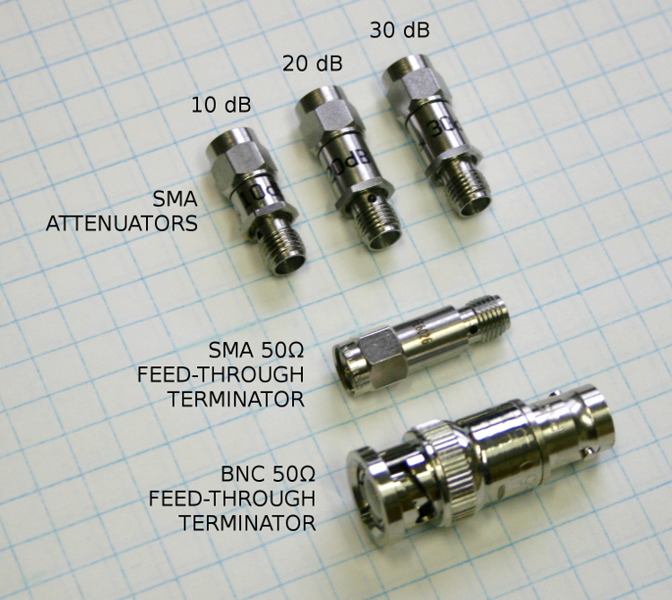
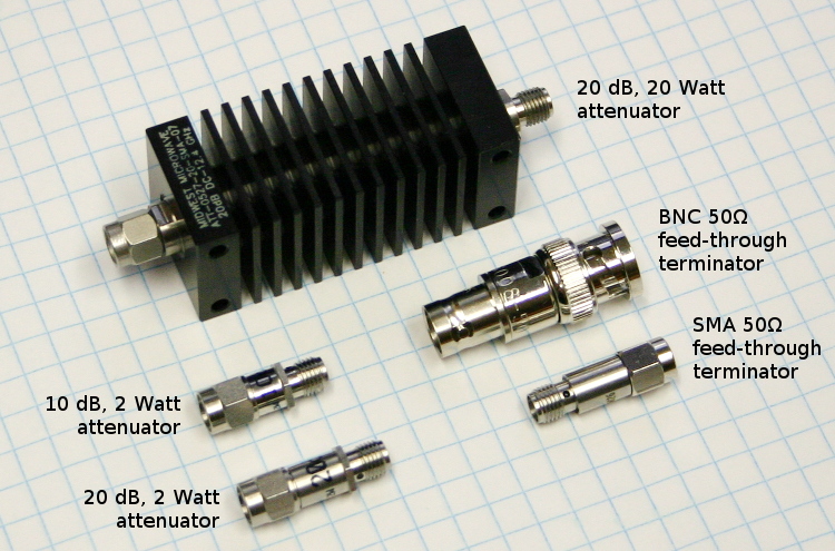
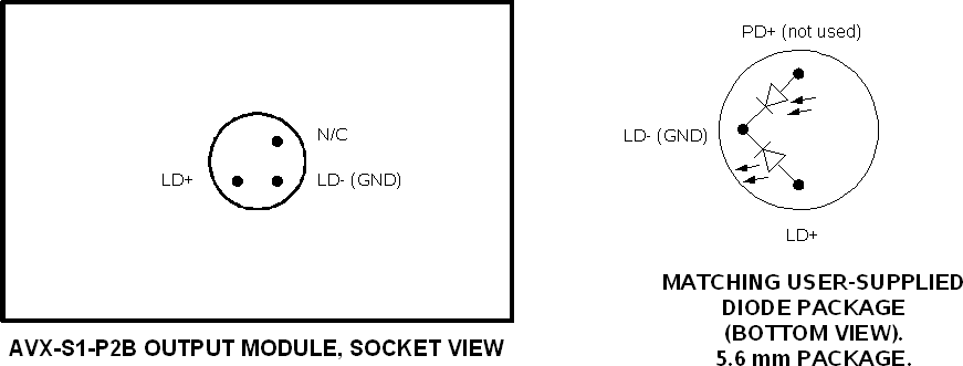
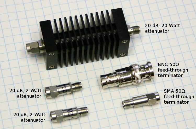